 English
 русский
 Español
 عربى
عربى3 Phase Transformer Selection: Connection Groups, Losses, and Testing Guide
Content
- 1 What a 3 Phase Transformer Delivers That Single-Phase Cannot
- 2 Delta vs Wye: Which 3 Phase Transformer Connection Fits Your Load
- 3 Dry-Type or Oil-Immersed: The Site Decides
- 4 Core Losses and Efficiency: The 20-Year Cost Driver
- 5 Verification Tests to Request Before Acceptance
- 6 FAQ: Sizing and Specifying a 3 Phase Transformer
A packaging plant added two extrusion lines with a combined motor load of 620 kVA, and the existing 400 V switchboard could not handle the inrush. The utility offered an 11 kV service drop, so the project team specified one 630 kVA 3 phase transformer instead of three single-phase units. The decision depends on three-phase power transformer engineering principles that reach beyond the nameplate rating: vector group, insulation medium, core material, and the test data that verify the quoted performance.
What a 3 Phase Transformer Delivers That Single-Phase Cannot
A 3 phase transformer transfers three-phase power between voltage levels in a single magnetic assembly, using about 15-20% less core steel and winding copper than three single-phase units of the same total rating. The saving comes from the shared three-limb core: the three phase fluxes are separated by 120 electrical degrees, their vector sum is zero at every instant, and the magnetic return paths cancel out.
The secondary windings feed industrial panels, motor control centers, and lighting circuits from a single tank or enclosure. Because the three phases share the core, a fault on one phase changes the flux distribution in the other two, which gives a three-phase transformer tighter voltage regulation under unbalanced loads than three independent single-phase units. This is why utilities and industrial plants standardize on three-phase units for ratings above roughly 25 kVA.
Delta vs Wye: Which 3 Phase Transformer Connection Fits Your Load
The vector group defines the phase shift between primary and secondary line voltages, the availability of a neutral, and the path that zero-sequence current takes during an unbalanced fault. Choosing Dyn11 instead of Yyn0 is not a preference issue; it determines whether the transformer can supply single-phase line-to-neutral loads safely.
In a delta winding, the phase windings connect end to end, so the line voltage equals the phase voltage, and triplen harmonics (3rd, 9th, 15th) circulate inside the delta instead of flowing into the source. In a wye winding, the phase ends meet at a star point that becomes the neutral; the line voltage is 1.732 times the phase voltage, which produces 400 V line-to-line and 230 V line-to-neutral on a 400 V secondary.
| Parameter | Delta (D) | Wye (Y) |
| Neutral | Not inherently available | Available at the star point |
| Line-to-phase relation | Line voltage = phase voltage | Line voltage = 1.732 x phase voltage |
| Triplen harmonics | Circulate within the delta | Flow into the neutral conductor |
| Ground-fault path | Requires separate earthing transformer | Directly groundable neutral |
| Common groups | Dd0, Dyn11 primary | Yyn0, Yd11 |
For an industrial supply at 11/0.4 kV, choose Dyn11 when any panel loads operate between phase and neutral, which is almost always the case. Yyn0 works only when the load is nearly balanced and the neutral current stays below roughly 10-15% of rated current. Dd0 is reserved for loads that need no neutral and accept an ungrounded or separately grounded system.
Dry-Type or Oil-Immersed: The Site Decides
The insulation and cooling medium determines where the transformer can be installed and what fire, containment, and maintenance systems the building must include. The site decides this choice before the kVA rating matters.
Dry-type fits indoor spaces
Suitable for basements, riser rooms, and occupied buildings because there is no oil to burn or contain.
- No oil containment pit or separator needed
- Higher first cost for the same rating
- Windings are moisture-sensitive; ambient air should be clean and dry
- Common in commercial towers, hospitals, tunnels, and offshore modules
Oil-immersed suits yards and substations
Lower first cost, high overload margin, and decades of utility maintenance practice behind it.
- Requires oil containment and fire separation depending on oil volume
- Needs periodic oil sampling and breakdown-voltage testing
- Carries a 10-15% price advantage over dry-type at the same kVA
- Standard for utility substations, industrial yards, and rural networks
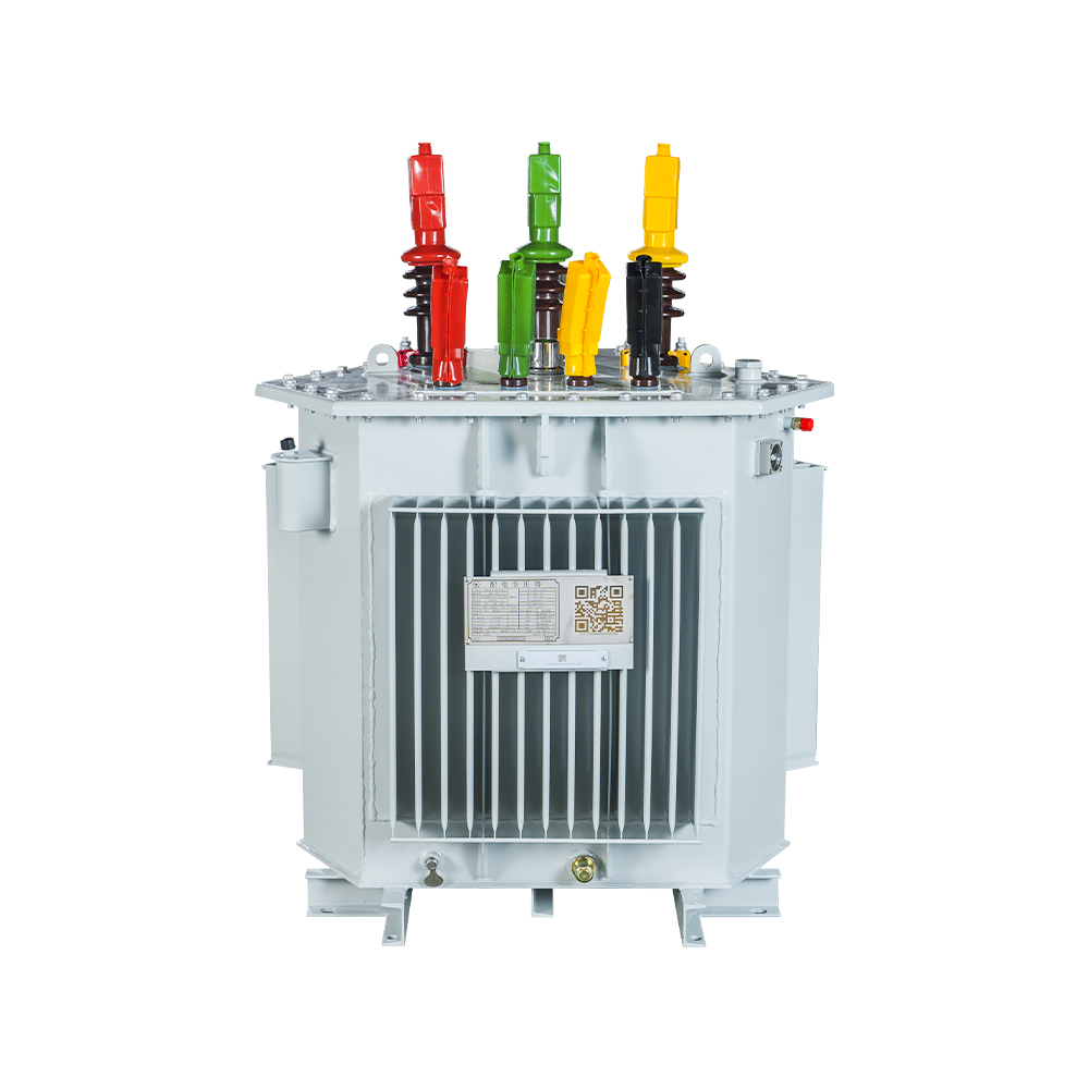
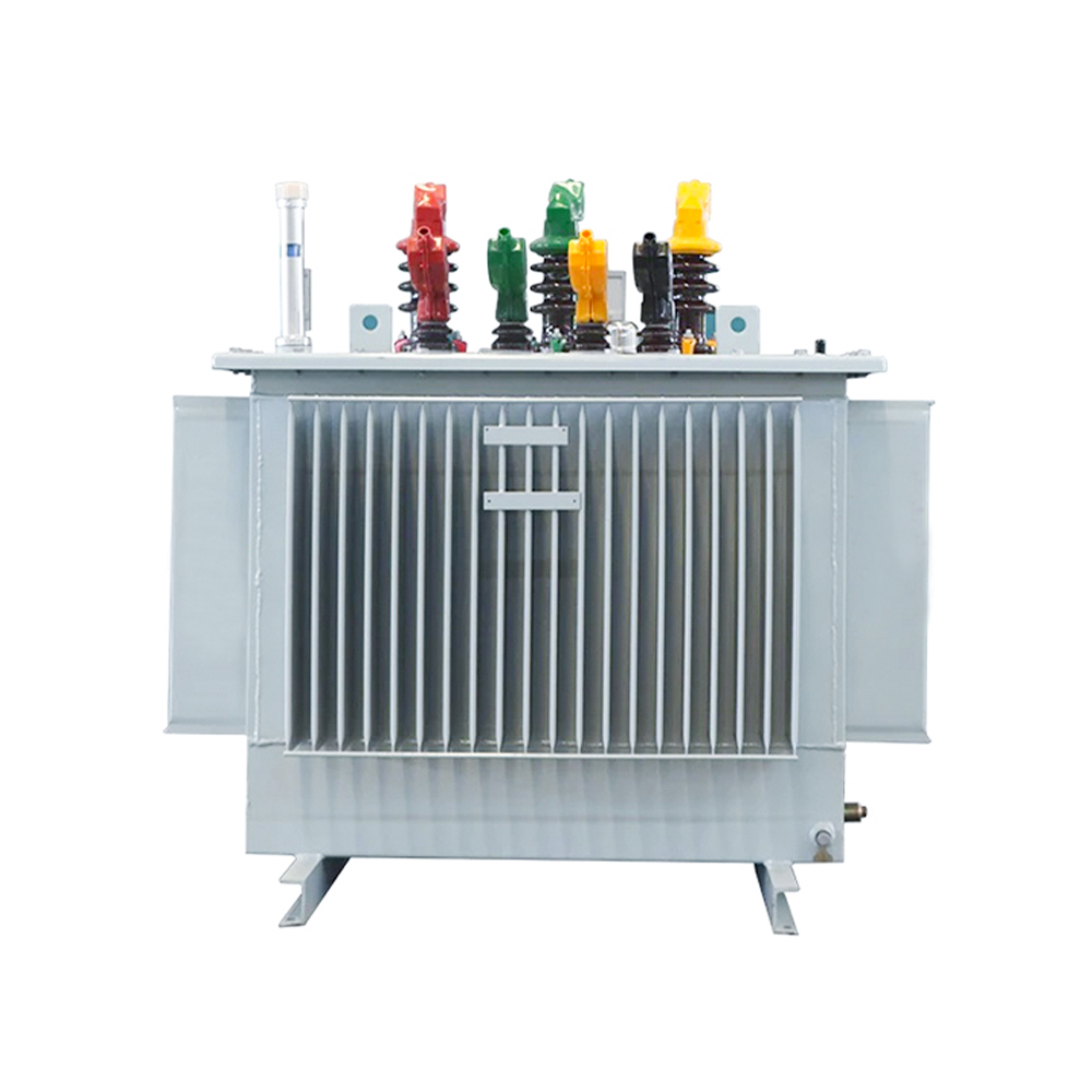 Oil-immersed Distribution Transformer with Silicon Steel Strip CoreThis unit is positioned as a low-cost, high-overload option for outdoor installations. The fully sealed design and corrugated plate cooling support reliable, low-maintenance operation on concrete plinths.View Product →
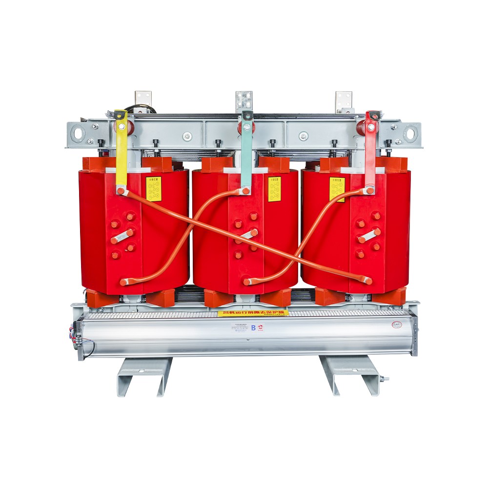
 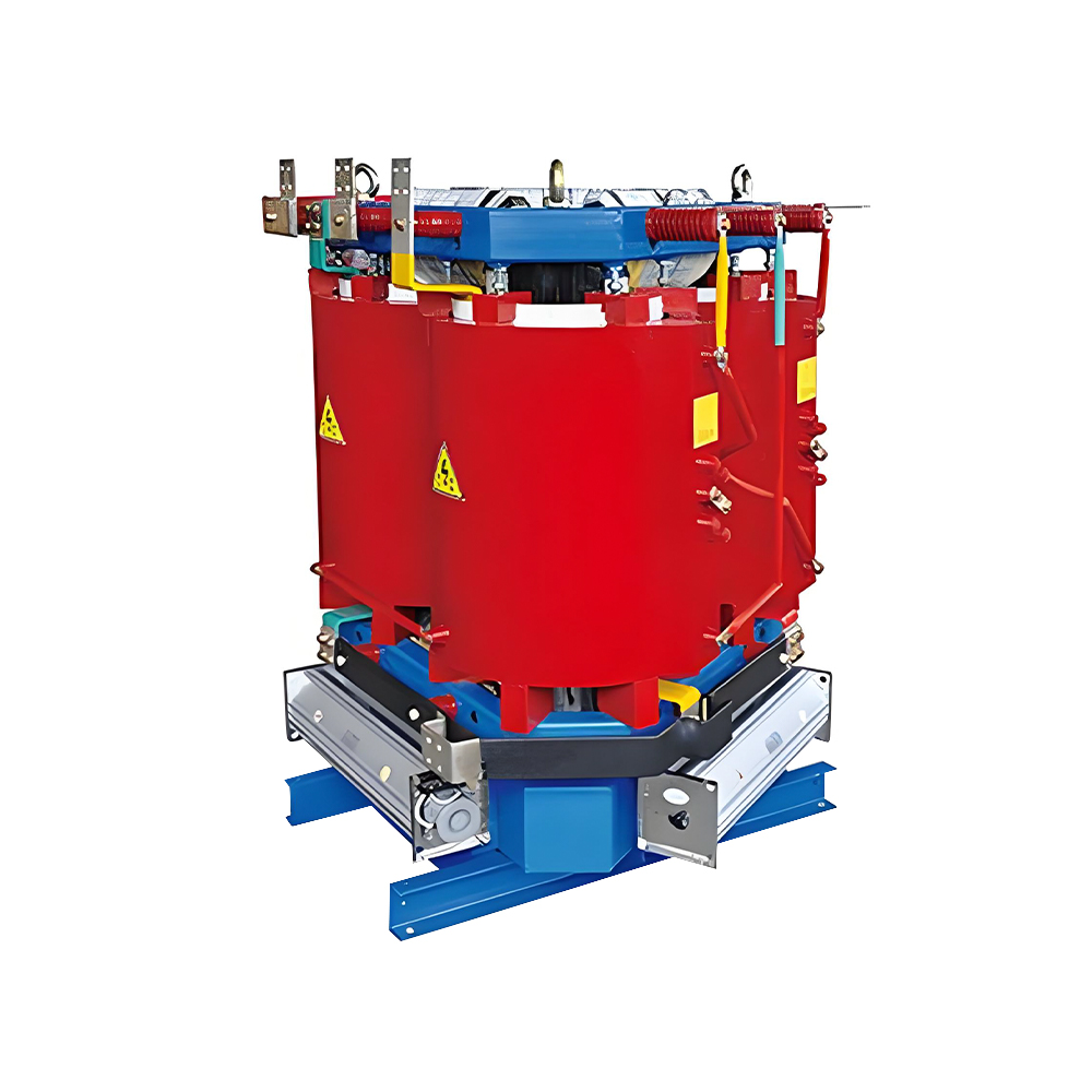 Amorphous Alloy Core Dry-type TransformerFor indoor or occupied-space applications, this dry-type design eliminates fire risk and fluid management. Ultra-low core losses and oil-free construction make it a strong energy-saving candidate here.View Product →
When the unit sits outdoors on a concrete plinth with a containment pit, an oil-immersed design is almost always the lower-cost route. When the transformer must be inside a building adjacent to occupied space, dry-type removes the fire risk and the fluid-management regime. Less-flammable ester fluids close the gap for indoor oil designs, but the tank, the pump, and the cooling system are still more equipment to maintain than a dry-type winding.
Core Losses and Efficiency: The 20-Year Cost Driver
No-load (core) losses run 24 hours per day, so the core material choice usually determines more of a transformer's lifetime energy cost than winding losses under typical operating profiles.
For a 630 kVA distribution transformer, a conventional grain-oriented silicon steel core (S13-class in the Chinese efficiency series) has no-load losses around 790 W. An amorphous alloy core, built from a rapid-quenched metallic ribbon, drops no-load loss to roughly 280 W for the same rating, a 65% reduction. Load (copper) losses stay nearly the same because they depend on winding conductor cross-section, not on the core material.
The payback math depends on the loading profile. When the average load stays below 40-50%, the amorphous core recovers its higher first cost through 24-hour core-loss savings, typically within three to seven years. When the transformer runs heavily loaded most of the time, load losses dominate, and the smarter investment is a lower-load-loss winding or a larger rating that runs at lower current density. A practical three-phase transformer selection guide should include the annual loading curve, not just the peak kVA.
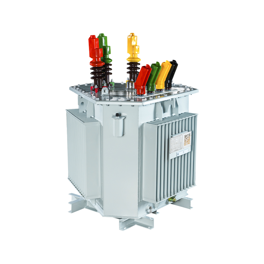 Amorphous Alloy Core Oil-immersed TransformerWhere loading stays below 40-50%, amorphous cores recover extra first cost through continuous core-loss savings. This unit pairs that benefit with oil-immersed robustness for outdoor service.View Product →
Verification Tests to Request Before Acceptance
The test report, not the nameplate, proves whether the transformer meets the quoted losses, impedance, and insulation withstand levels. A routine factory report is standard, but the buyer should review the numbers before the unit ships. A reputable manufacturer such as Jiangsu Hengyuan Transformer Co., Ltd. can supply the routine report with every unit and the type-test certificates on request.
- No-load loss and no-load current at rated voltage and rated frequency
- Load loss and impedance voltage at rated current, corrected to 75 degrees C for oil units or 120 degrees C for dry-type
- Winding resistance on all phases with phase imbalance below 2%
- Insulation resistance at 2.5 kV plus induced voltage withstand at twice rated voltage
- Turns-ratio verification on every tap and vector-group confirmation by phase-angle measurement
- Oil breakdown voltage and dissolved gas analysis for oil-immersed units at commissioning
| Test parameter | Silicon steel core | Amorphous core |
| No-load loss | 790 W | 280 W |
| Load loss at reference temperature | 6,200 W | 6,200 W |
| Impedance voltage | 4.5% | 4.5% |
| No-load current | 1.2% | 0.4% |
Impedance voltage matters for parallel operation: two units with mismatched impedance share load unevenly and produce circulating current. Voltage ratio accuracy affects voltage drop at the load terminals, and insulation test results establish the baseline for future condition monitoring. When the unit will serve critical process loads, ask for type-test certificates covering temperature rise, lightning impulse, and short-circuit withstand.
FAQ: Sizing and Specifying a 3 Phase Transformer
What size 3 phase transformer do I need for a mixed industrial load?
Add the nameplate kVA of all connected loads, apply the demand factor for the specific process, and divide by the average power factor (typically 0.85-0.95). Add a 15-20% growth margin, then round up to a standard rating such as 400, 630, 800, or 1,000 kVA. A measured peak demand of 450 kVA therefore points to a 630 kVA unit, leaving room for motor inrush and future extensions.
Can three single-phase transformers replace one 3 phase transformer?
Electrically and mechanically, yes, and this is sometimes done for spare-part flexibility on very large ratings. However, three separate units cost 15-20% more in active material, occupy more ground area, and need three protection and tap-changing systems. For ratings up to several MVA, a single three-phase unit is almost always the more economical and compact choice.
What does Dyn11 mean and why is it so common?
Dyn11 describes a transformer with a delta-connected primary, a wye-connected secondary with the neutral brought out, and a 30-degree phase shift that places the secondary voltage at the 11 o'clock position on a clock diagram. It is the standard connection for 11/0.4 kV distribution transformers because the delta blocks triplen harmonics and the wye supplies balanced single-phase 230 V loads.
How much can an amorphous core reduce no-load loss?
For a typical 630 kVA distribution transformer, an amorphous alloy core cuts no-load loss from roughly 790 W to about 280 W, a 65% drop. The payback period depends on the loading profile and local energy tariffs; at low average load factors, the savings usually recover the extra first cost within three to seven years.

 Contact

Contact
-

wxj.810@163.com
-

+86-523-82962116
-

No. 111, Guoqing East Road, Chengdong High-tech Industrial Park, Taixing City, Jiangsu Province, China
Copyright © 2026 by Jiangsu Hengyuan Transformer Co., Ltd. Rights Reserved.
