 English
 русский
 Español
 عربى
عربىThree Phase Power Transformer: Core Losses, Connections, and Selection Criteria
Content
A 1000 kVA three phase power transformer that stays energized for 25 years will burn through more money in core losses than its own purchase price, frequently double. That statistic explains why specification decisions have shifted: engineers no longer choose on first cost alone, but on the combined behavior of core material, winding configuration, cooling class, and lifetime efficiency.
01 How a Three Phase Power Transformer Works
A three phase power transformer is an electromagnetic device that transfers electrical energy between two three-phase AC systems through magnetic induction. It performs the same voltage transformation job as a single-phase unit, but with three primary and three secondary windings arranged on one laminated magnetic core.
The core is built from grain-oriented electrical steel or amorphous metal ribbon, with three limbs that carry the magnetic flux. Each limb links one primary and one secondary winding. With a balanced three-phase supply, the flux in each limb is displaced by 120 electrical degrees from the others. Because the voltage ratio equals the turns ratio, stepping down from 10 kV to 0.4 kV requires a 25:1 turns ratio in each phase.
Three-phase transmission exists because it is quantitatively more efficient. For the same conductor mass and insulation level, a three-phase line delivers about 1.73 times more power than a comparable single-phase system. That factor appears at every decision point: generators, grid substations, industrial mains, and building services all standardize on three-phase power, and the interface into those systems is usually a three phase power transformer.
In short, the three phase power transformer converts voltage level while preserving the 120-degree phase relationship between the three lines.
02 Oil-Filled vs Dry-Type: Choosing a Platform
The first structural decision is the medium used for insulation and cooling: liquid-filled or dry-type. Each platform is well proven; the right answer depends on installation environment, capacity, and fire safety requirements.
Oil-filled transformers use mineral oil or ester fluid to insulate the windings and carry heat to the tank surface, where radiators or fans dissipate it. They dominate utility substations and high-capacity industrial sites because liquid cooling is far more efficient than air cooling above 2,000 kVA. Dry-type transformers use air or cast resin insulation. They are the norm in commercial buildings, hospitals, data centers, and indoor manufacturing plants, where the absence of combustible fluid simplifies fire protection and allows installation without bunding or fire walls.
| Attribute | Oil-Filled | Dry-Type |
| Typical capacity | 50 kVA to over 100 MVA | 50 kVA to about 20 MVA |
| Cooling methods | ONAN, ONAF, OFAF | Natural air, forced air |
| Indoor installation | Requires fluid containment | Allowed without containment |
| Short-term overload | 1.3x for 2 h typical | Limited by winding temperature |
| Relative first cost | Lower per kVA | 20-40% higher per kVA |
| Typical location | Outdoor substations | Indoor plant rooms |
For most onsite distribution between 100 kVA and 2,500 kVA, both options can work. The decision comes down to building code restrictions, available space, and weather exposure. A liquid-filled unit can sit outdoors with simple fencing; a dry-type unit belongs indoors or inside a weatherproof enclosure.
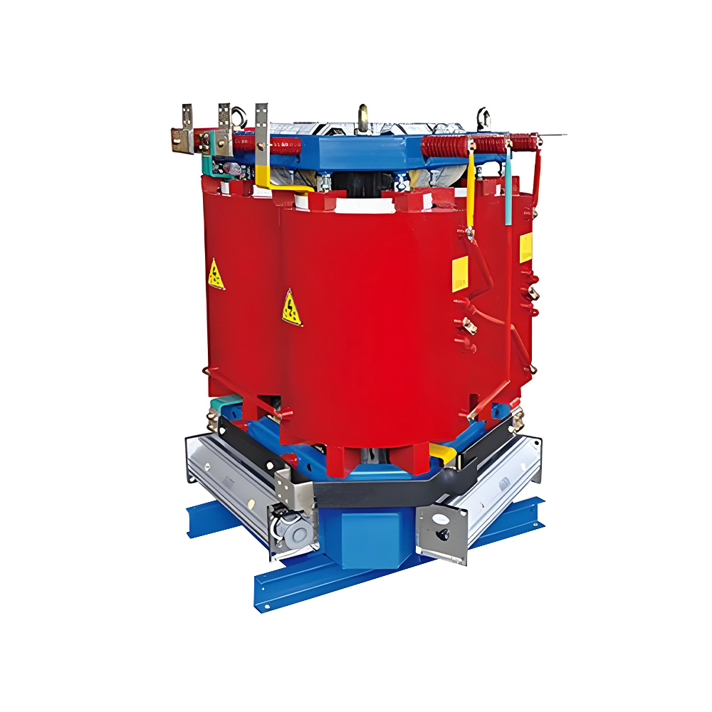
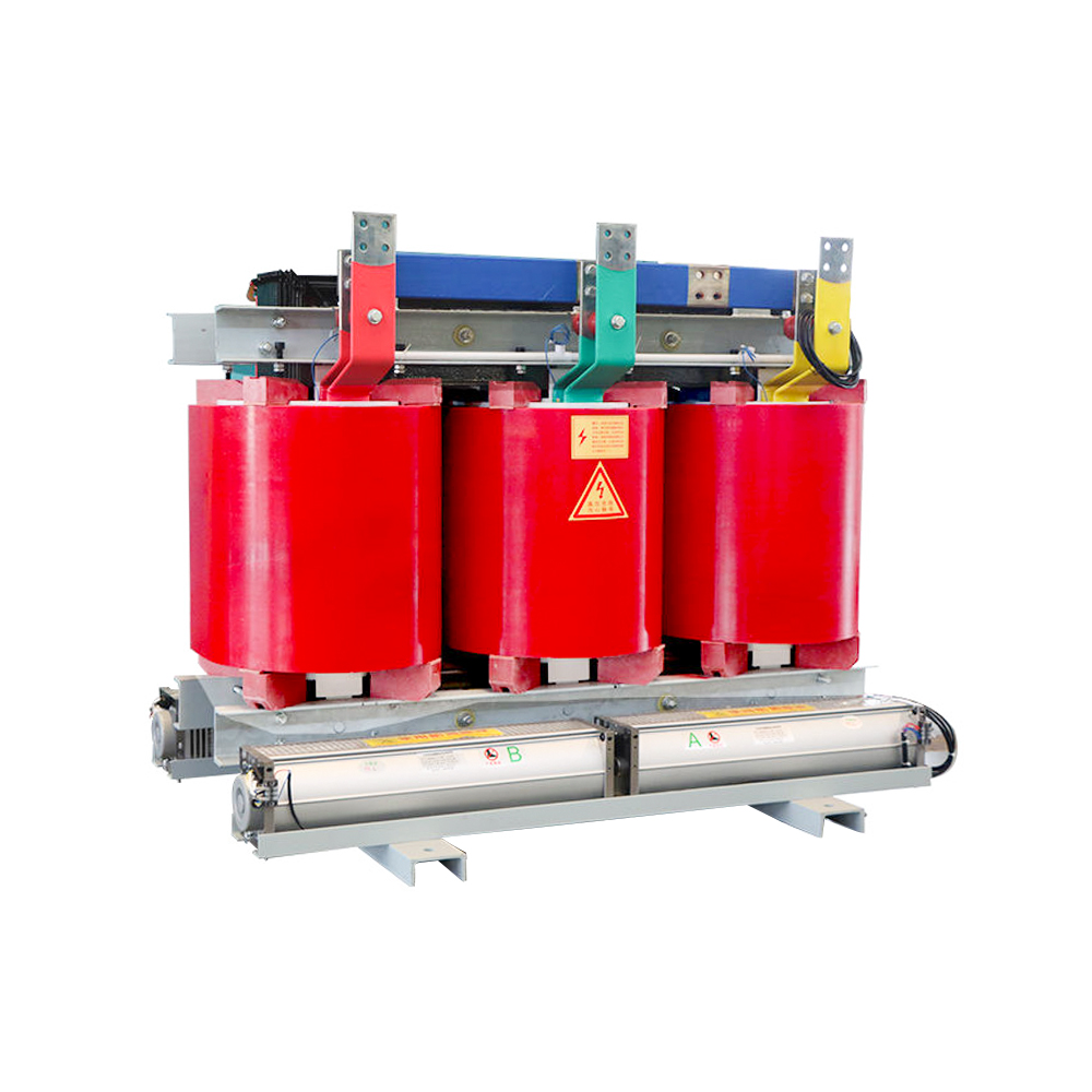 Three-phase Dry-type Transformer with Silicon Steel CoreThis epoxy-cast dry-type transformer suits indoor or weatherproof installations where space and safety matter. Its low no-load loss design addresses the operating costs discussed here, making it a practical choice for urban and high-requirement sites.View Product →
03 Core Material: Amorphous vs Silicon Steel Losses
Core material determines no-load loss, which penalizes the operator every hour the transformer is connected, whether loaded or not. No-load loss dominates the operating cost of distribution transformers, which typically run at low average loading.
Grain-oriented silicon steel has been the standard core material for decades, with no-load losses around 0.2 to 0.5 percent of rated capacity depending on grade. Amorphous alloy cores, made from rapidly solidified metal ribbon, reduce those losses by 60 to 80 percent. The trade-off is a larger core cross-section and a higher acquisition cost that must be recovered through energy savings.
On a 1,000 kVA transformer, a conventional silicon-steel core dissipates roughly 1.5 kW continuously. An amorphous core reduces that to about 700 W, saving approximately 7,000 kWh per year at an 80 percent loading factor. At 0.12 USD per kWh, that is about 840 USD in annual savings before demand charges or carbon pricing.
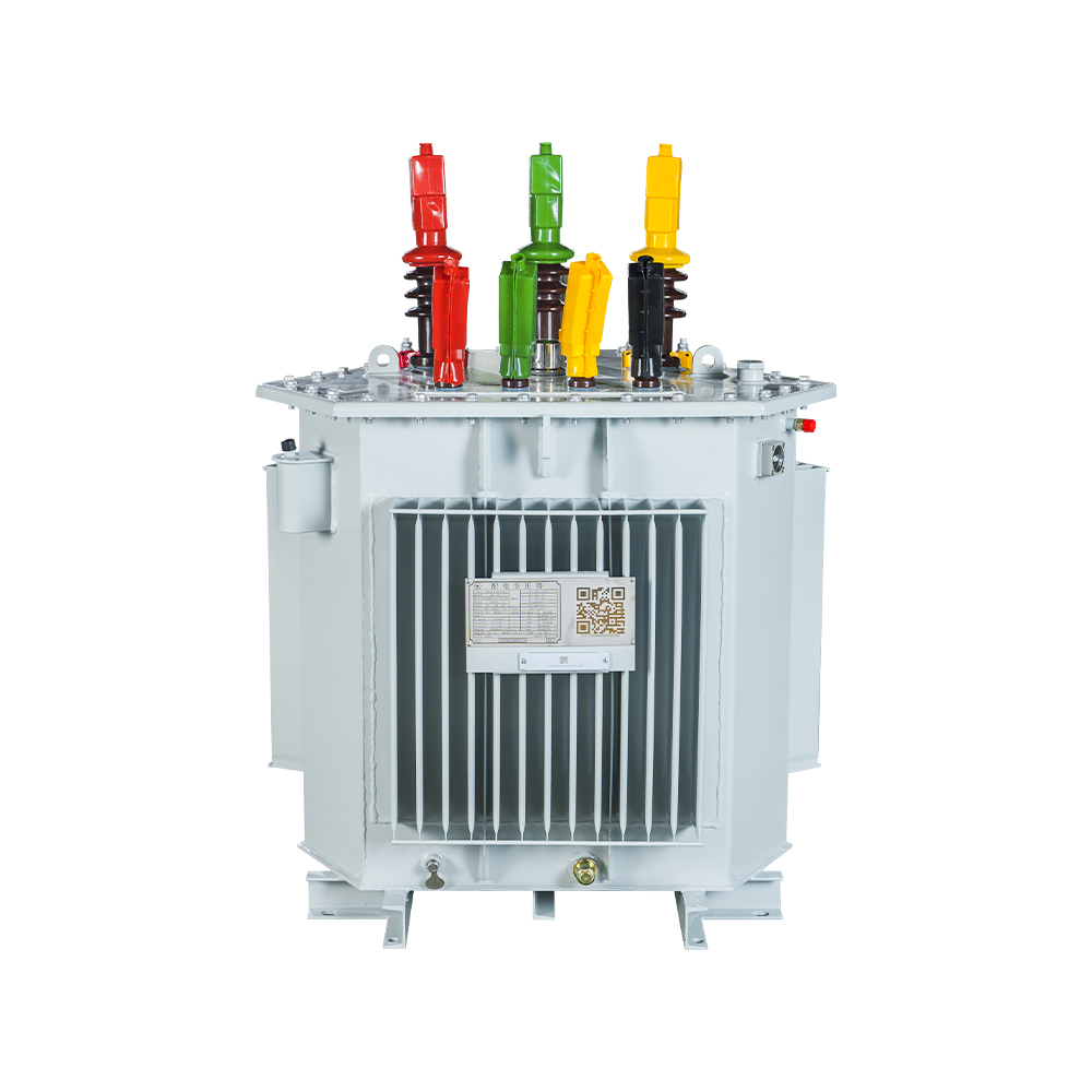
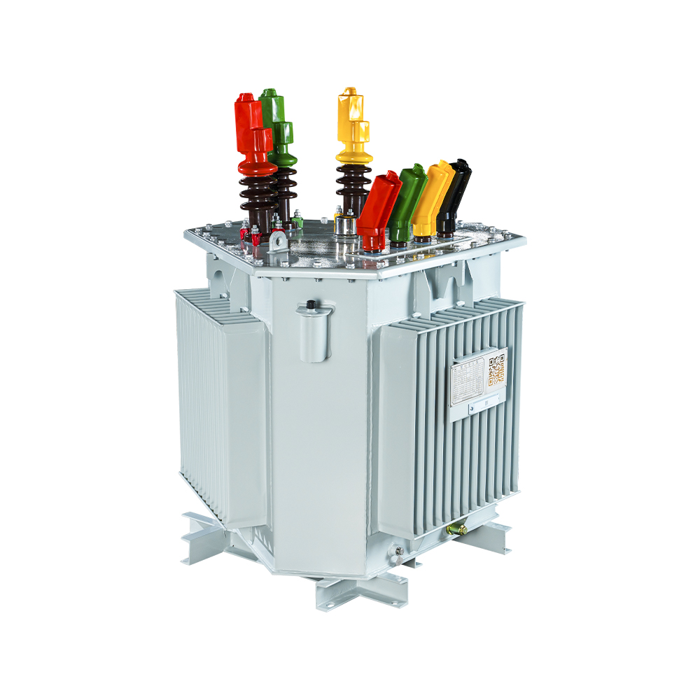 Amorphous Alloy Core Oil-immersed TransformerWith ultra-low core loss, this unit directly reduces continuous energy waste outlined in the preceding comparison. Its weather-resistant construction also fits outdoor placement, offering substantial annual savings while keeping noise and temperature rise low.View Product →
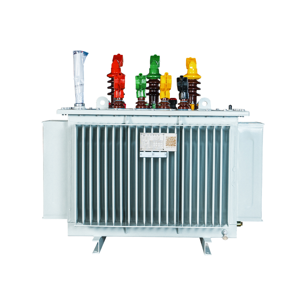
 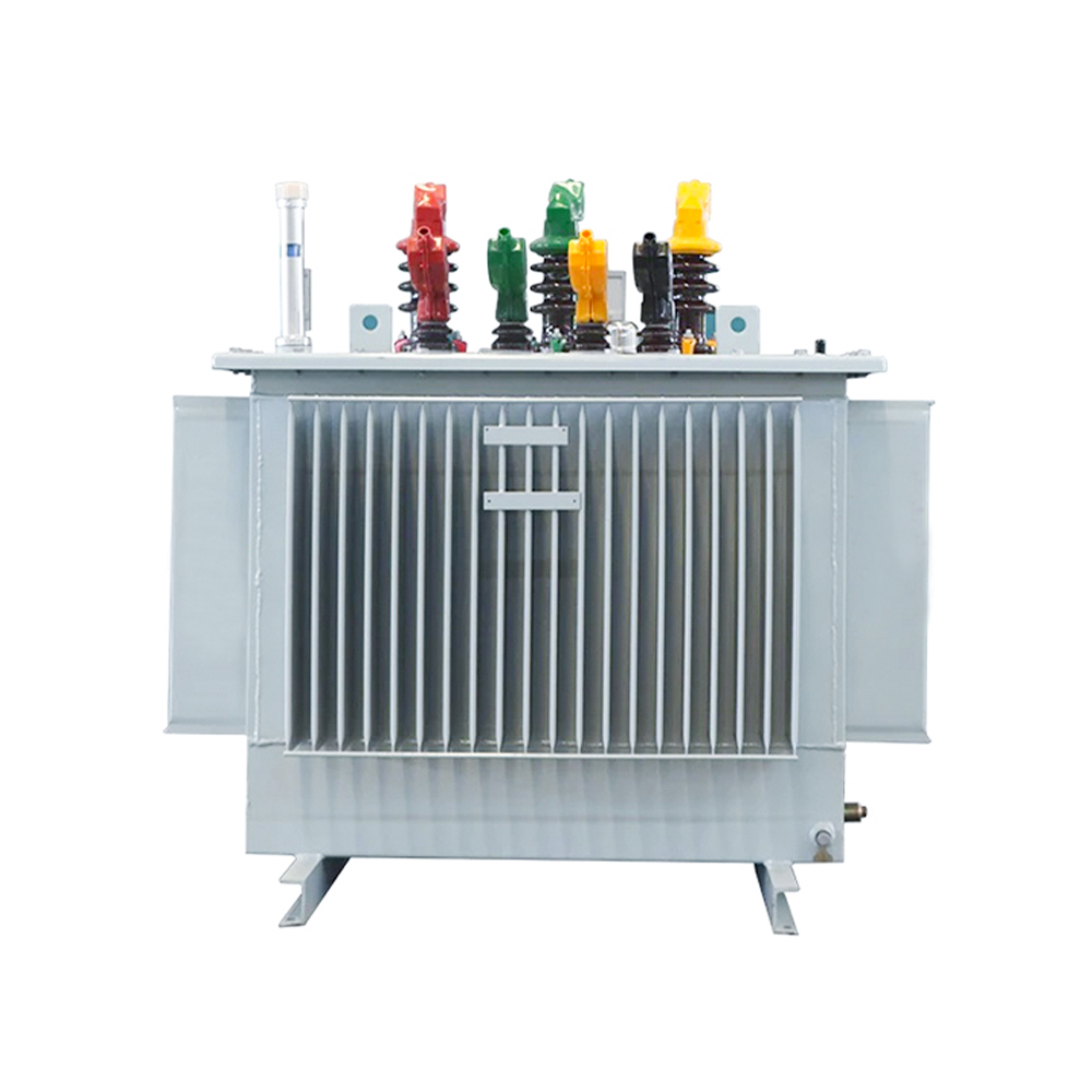 Oil-immersed Transformer with Silicon Steel Strip CoreA fully sealed design using high-performance silicon steel and oxygen-free copper minimizes no-load loss and maintenance. This transformer is a reliable outdoor option for distribution duties, supporting the efficiency considerations raised in the surrounding text.View Product →
04 Delta and Wye: Connection Configurations
The winding connection establishes neutral availability, phase shift, zero-sequence behavior, and harmonic interaction. These are operational characteristics, not minor nameplate details.
In a delta connection, each winding connects corner-to-corner to form a closed triangle. Delta provides no neutral, is normally used on the high-voltage side, and confines triplen harmonic currents so they circulate internally rather than entering the grid. In a wye connection, one end of each winding ties to a common neutral point. The wye side provides the neutral conductor for single-phase loads and permits a higher phase-to-neutral voltage.
| Vector group | HV/LV connection | Phase shift | Typical use |
| Dyn11 | Delta / Wye | 330 degrees | Standard distribution |
| Yyn0 | Wye / Wye | 0 degrees | Small distribution |
| YNd11 | Wye / Delta | 330 degrees | Step-up, grounding |
| Dd0 | Delta / Delta | 0 degrees | Industrial networks |
Vector group is the standardized notation that describes how the high-voltage and low-voltage windings are connected and the phase shift between them, expressed as a clock-hour number.
05 Selection Criteria for a Three Phase Power Transformer
Five parameters specify a three phase power transformer: kVA capacity, voltage ratio, vector group, impedance, and cooling class. Application factors such as ambient temperature, altitude, and harmonic load modify the final rating.
- Capacity: size for measured peak demand plus 20-25% growth margin.
- Voltage ratio: primary matches the utility feeder; secondary matches the load (400 V, 690 V, or 11 kV).
- Impedance: 4-6% for distribution; higher values limit fault current but increase voltage regulation.
- Vector group: Dyn11 for most distribution duties.
- Cooling class: ONAN as standard; add fans or pumps for planned seasonal peaks.
Oversizing increases no-load loss because core loss exists whether the transformer is loaded or not. Undersizing reduces efficiency and accelerates insulation aging. That trade-off is why many specifications now demand amorphous cores and a loading band between 60 and 80 percent of rated capacity.
For 6 to 35 kV distribution duty, Jiangsu Hengyuan Transformer Co., Ltd. builds both oil-filled and dry-type platforms with silicon-steel or amorphous cores, which simplifies comparison at the bid stage. A deeper treatment of the engineering trade-offs appears in our three phase power transformer selection guide, which walks through the calculations behind each parameter.
Spec rule of thumb: size the transformer to run between 60% and 80% of rated capacity in normal service. That band balances efficiency, temperature rise, and future headroom.
06 Frequently Asked Questions
Can three single-phase transformers replace one three phase power transformer?
Yes, three identical single-phase units can be banked into a three-phase bank. That approach offers per-phase redundancy and easier replacement, but it costs roughly 20 to 30 percent more, occupies more floor space, and has higher total losses than a single three-phase unit of the same rating.
What does Dyn11 mean on a rating plate?
Dyn11 is the vector group notation: D means the high-voltage winding is delta-connected, y means the low-voltage winding is wye-connected, n means the wye neutral is brought out, and 11 indicates the clock-hour phase shift of 330 degrees between the high-voltage and low-voltage sides.
Amorphous core or silicon steel core, which is better?
Amorphous cores cut no-load loss by 60 to 80 percent and win on lifecycle cost when the transformer runs continuously at low load. Silicon steel costs less upfront and permits a more compact design. For utilities and high-run-hour industrial sites, amorphous alloy is usually the better total-cost decision.
Why do no-load losses matter so much?
No-load losses occur 24/7 whenever the transformer is energized, independent of load. Over a 25-year service life, they can exceed the transformer purchase price, which makes core loss the dominant term in total cost of ownership.
Recommended Products

 Contact

Contact
-

wxj.810@163.com
-

+86-523-82962116
-

No. 111, Guoqing East Road, Chengdong High-tech Industrial Park, Taixing City, Jiangsu Province, China
Copyright © 2026 by Jiangsu Hengyuan Transformer Co., Ltd. Rights Reserved.
