 English
 русский
 Español
 عربى
عربىThree Phase Distribution Transformer Guide: Types, Losses, and Selection
Content
- 1 What a Three Phase Distribution Transformer Actually Does
- 2 Oil-Immersed or Dry-Type: The First Branch in Three Phase Distribution Transformer Selection
- 3 Amorphous Alloy or Silicon Steel Core: Where Iron Loss Is Won or Lost
- 4 The Two Loss Numbers That Decide Operating Cost
- 5 From Specification to Installation: Matching the Unit to the Real Load
- 6 Three Phase Distribution Transformer FAQ
- 6.1 How does a three phase distribution transformer differ from a single phase transformer?
- 6.2 Can three single-phase transformers replace one three phase distribution transformer?
- 6.3 Why is Dyn11 the most common connection for three phase distribution transformers?
- 6.4 How much can an amorphous core save in real money?
A 630 kVA three phase distribution transformer with a 1.2 kW no-load loss consumes about 10,500 kWh per year before a single load connects. At 0.10 USD per kWh, that is more than 1,000 USD spent annually on keeping the core magnetized. For distribution engineers, procurement teams, and plant managers, the three phase distribution transformer is where small specification decisions become large operating costs. Jiangsu Hengyuan Transformer Co., Ltd., a manufacturer of transformers and switchgear for 6-35 kV networks, builds oil-immersed and dry-type units with amorphous alloy and silicon steel cores.
What a Three Phase Distribution Transformer Actually Does
A three phase distribution transformer is a static electromagnetic device that steps down medium voltage, usually 6 kV to 35 kV, to a 400/230 V level for industrial, commercial, and residential customers.
The unit places three primary windings and three secondary windings on a common three-limb core. Alternating flux from the primary induces voltage in the secondary at the same frequency, so the unit trades voltage for current according to the turns ratio. The Dyn11 vector group is standard: the HV side is delta-connected, and the LV side is wye-connected with the neutral brought out for 230 V single-phase loads and earthing.
- Primary ratings that dominate practical projects: 6 kV, 10 kV, 20 kV, and 35 kV classes
- Secondary delivery: three-phase 400 V plus a solidly earthed neutral
- Common distribution rating range: 50 kVA to 2,500 kVA
- Full-load efficiency above 98 percent, with the remaining losses split between core and windings
Oil-Immersed or Dry-Type: The First Branch in Three Phase Distribution Transformer Selection
Choose an oil-immersed transformer when the unit will sit outdoors or in a dedicated substation; choose dry-type only when the installation is indoor and fire safety, floor loading, or environmental rules rule out oil.
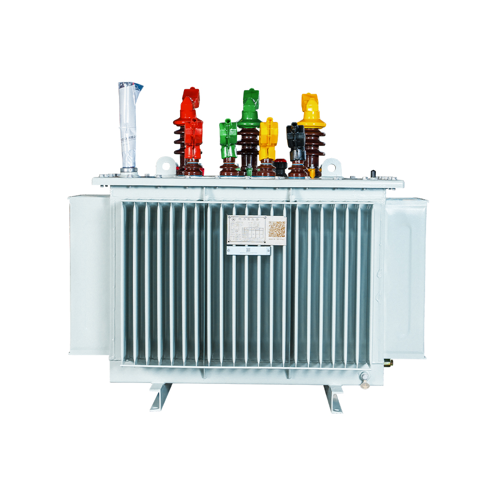
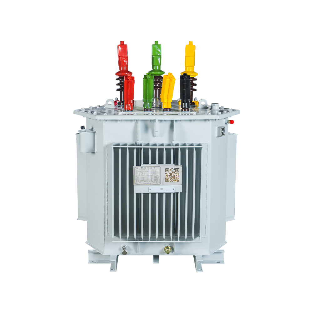
Oil-filled units use mineral oil or synthetic ester for insulation and cooling. The oil carries heat to the tank wall, where fins or radiators dissipate it under the ONAN cooling class. Oil-immersed three phase distribution transformers in the 6-35 kV class cover roughly 30 kVA to 2,500 kVA and dominate utility networks because they are robust and the cheapest per kVA. The trade-off is containment: the pad needs an oil-collection pit or bunding.
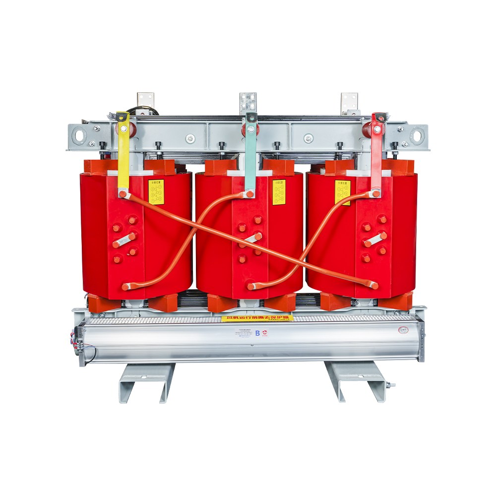
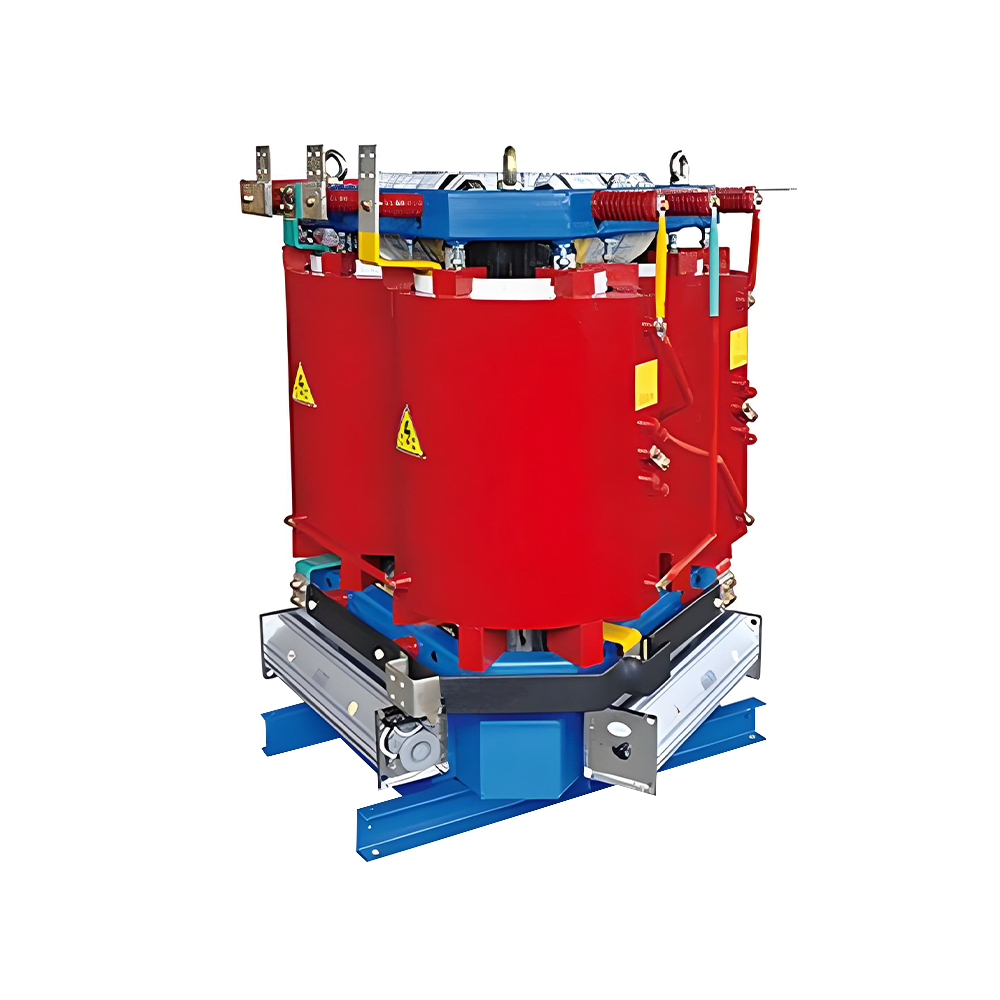
Dry-type units replace oil with cast resin or air insulation. They are specified inside commercial buildings, tunnels, and marine structures where a flammable liquid is unacceptable. Dry-type transformers carry a lower fire load and need almost no fluid maintenance, but they cost more per kVA and their thermal capacity is more sensitive to ambient temperature. For outdoor distribution duty, oil-immersed remains the correct first consideration.
- Insulated and cooled by mineral oil or ester, ONAN
- Typical range 30-2,500 kVA
- Outdoor pad or pole substations
- Requires oil containment and periodic oil testing
- Lowest first cost per kVA
- Cast-resin or air insulation, no liquid
- Typical range 100-3,150 kVA
- Indoor, high-rise, tunnel, marine use
- Low fire load, minimal fluid maintenance
- Higher first cost, thermally sensitive
| Attribute | Oil-immersed | Dry-type |
| Insulation and cooling | Mineral oil or ester, ONAN | Cast resin or air, AN/AF |
| Typical rating | 30-2,500 kVA | 100-3,150 kVA |
| Main installation | Outdoor substations and poles | Indoor enclosed spaces |
| Fire risk | Higher, requires containment | Low fire load |
| Maintenance | Oil tests, breather service | Cleaning and ventilation checks |
| Relative cost per kVA | Baseline | 1.3-1.8 times baseline |
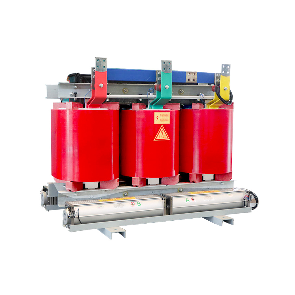 Three-Phase Dry-Type Transformer with Silicon Steel CoreThis epoxy-cast dry-type distribution transformer suits indoor and high-safety locations where oil is prohibited, offering flame-retardant construction and low maintenance for commercial, tunnel, and marine applications.View Product →
Amorphous Alloy or Silicon Steel Core: Where Iron Loss Is Won or Lost
Amorphous alloy cores reduce no-load loss by 70 to 80 percent compared with grain-oriented silicon steel, and no other single specification change in a three phase distribution transformer produces that large a reduction in lifetime running cost.
No-load loss, also called iron loss, is absorbed by the core whenever the transformer is energized, regardless of load. It consists of hysteresis loss and eddy-current loss. Amorphous metal is a ferromagnetic alloy supplied as a ribbon about 25-30 microns thick, roughly one-tenth the thickness of grain-oriented silicon steel. The thin ribbon and low coercivity cut both loss components, so an amorphous core consumes about one-quarter of the excitation energy of a silicon steel core at the same kVA.
Relative no-load loss of a typical 630 kVA three phase distribution transformer core, normalized to 100 percent for CRGO silicon steel.
The trade-off is commercial, not electrical. Amorphous cores cost more to build, and lower saturation induction means a slightly larger core cross-section. Distribution transformers stay energized continuously but load only 30-60 percent on average, so no-load loss dominates total loss. The 0.85 kW saving on a 630 kVA unit pays the premium back in three to five years, then keeps saving for the rest of a 20-year life. For utilities with hundreds of units, amorphous fleets are one of the most direct ways to cut distribution network losses.
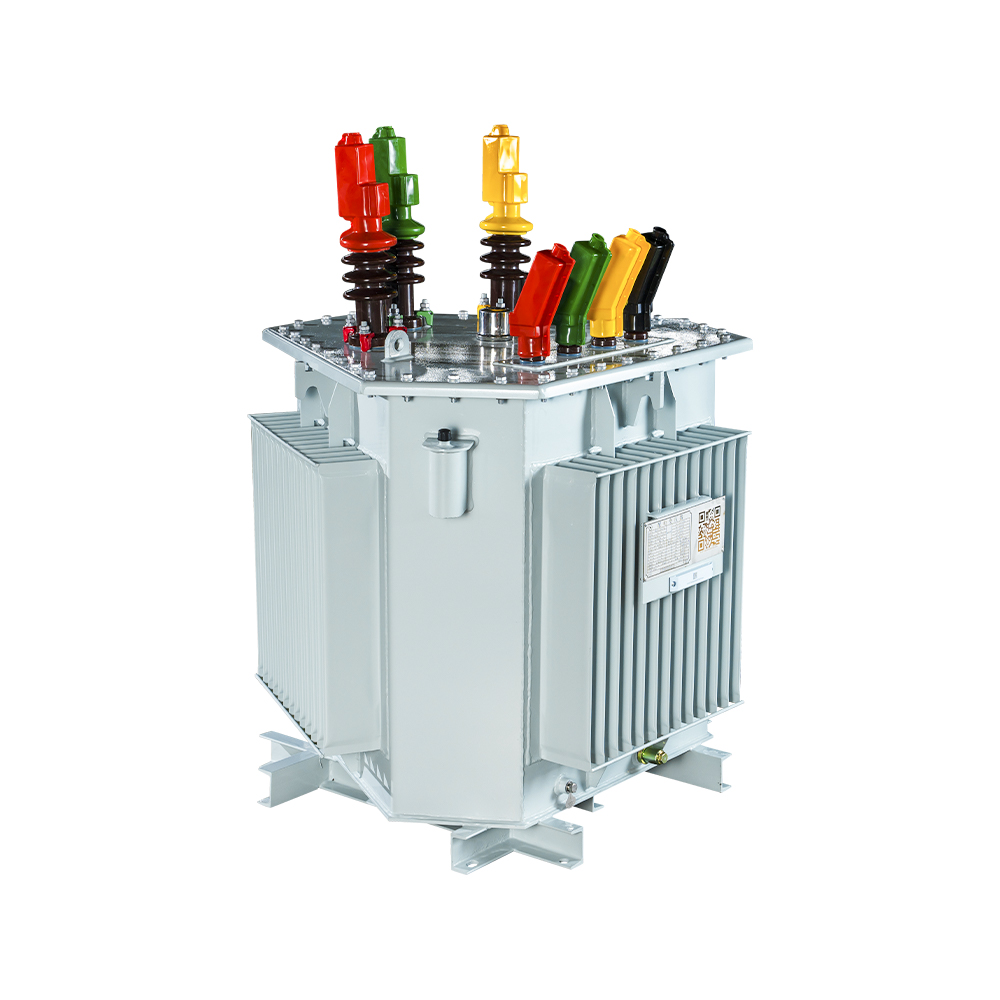 Amorphous Alloy Core Oil-Immersed TransformerWith ultra-low no-load losses from amorphous ribbon and advanced noise reduction, this oil-immersed unit delivers significant lifetime energy savings, making it ideal for utilities seeking to cut distribution network losses.View Product →
The Two Loss Numbers That Decide Operating Cost
No-load loss and load loss determine the operating cost of a three phase distribution transformer; the purchase price is the smallest component of 20-year ownership cost, not the largest.
Load loss is winding copper loss at rated current and rises with the square of the load. No-load loss runs continuously, so it dominates the bill at low and average utilization, exactly where most distribution transformers operate. The figures below are typical for the 6-35 kV class at standard loss levels.
| Rated power (kVA) | No-load loss, silicon steel (W) | No-load loss, amorphous (W) | Load loss at full load (W) | Annual no-load energy, silicon (kWh) |
| 100 | 320 | 90 | 1,500 | 2,803 |
| 250 | 610 | 170 | 3,250 | 5,344 |
| 400 | 840 | 240 | 4,600 | 7,358 |
| 630 | 1,200 | 350 | 6,600 | 10,512 |
| 1,000 | 1,700 | 500 | 9,800 | 14,892 |
Total cost of ownership is TOC = price + A x no-load loss + B x load loss, where A capitalizes one kilowatt of iron loss at the energy tariff over the project life, and B capitalizes one kilowatt of copper loss, including demand charges. Utility tenders publish loss-capitalization factors in the bid document; buyers who ignore them still pay the correct loss price, only to the electricity company instead of to the transformer supplier.
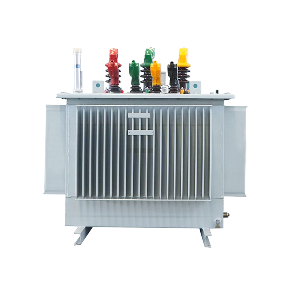 Oil-Immersed Transformer with Silicon Steel Strip CoreFeaturing high-performance silicon steel and a fully sealed structure, this oil-immersed transformer reduces losses and maintenance while offering robust short-circuit resistance, suitable for reliable distribution duty.View Product →
From Specification to Installation: Matching the Unit to the Real Load
The correct rating is the smallest standard kVA that carries the expected peak load within winding temperature limits and leaves a defined margin for growth; oversizing wastes money, and undersizing shortens transformer life.
- Confirm primary and secondary voltages. Record the feeder voltage, for example 10 kV or 35 kV, and the delivery voltage of 400/230 V with neutral.
- Calculate the peak demand. Sum connected loads and apply a realistic diversity factor rather than adding nameplate ratings.
- Add load-growth margin. Common practice is 15-25 percent above the five-year peak forecast.
- Set impedance per network rules. Standard impedance for 10 kV distribution units is about 4 percent.
- Compare loss classes with the utility loss-capitalization formula. Specify an amorphous core when payback is under five years.
- Select the mechanical arrangement: pole-mount, pad-mount, or a compact substation integrating transformer, ring-main unit, and LV switchgear.
For rural grid expansion and industrial plants, a compact substation package cuts site installation time: the transformer arrives with the HV ring-main unit and LV switchgear already connected and type-tested in the factory.
Three Phase Distribution Transformer FAQ
How does a three phase distribution transformer differ from a single phase transformer?
A single-phase transformer has one primary and one secondary winding and delivers 230 V single-phase power. A three phase distribution transformer has three primary and three secondary windings on a common core and delivers 400 V three-phase power plus a neutral. For the same kVA, the three-phase unit is lighter, more efficient, and uses less conductor material.
Can three single-phase transformers replace one three phase distribution transformer?
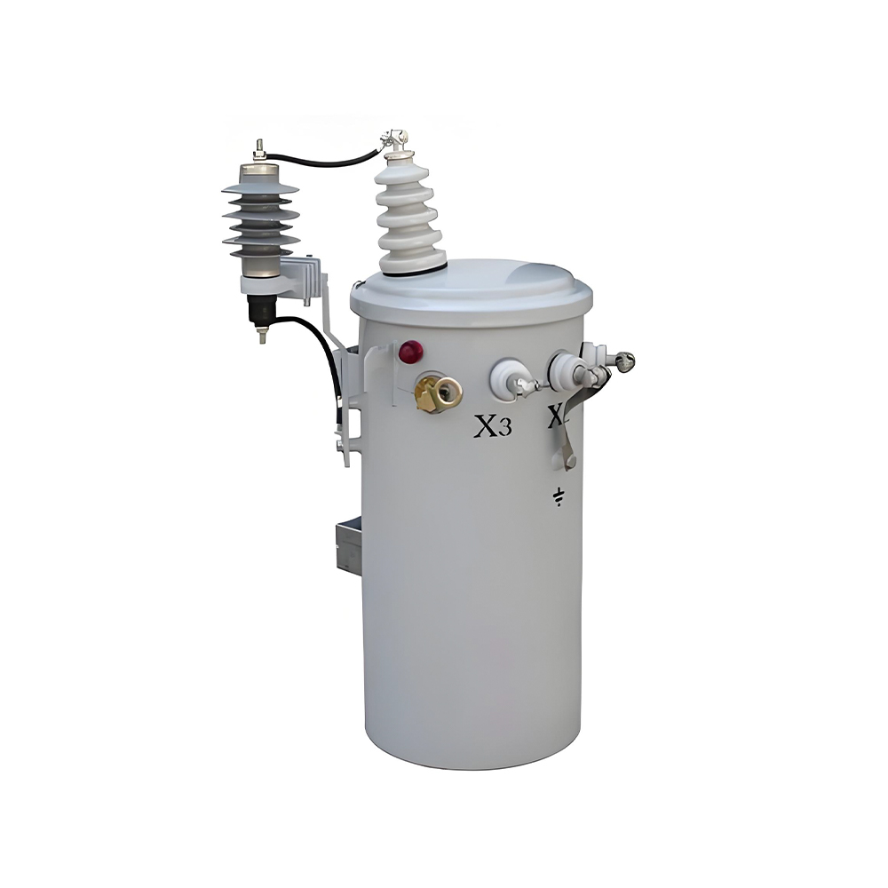
Yes, and some North American systems still use a transformer bank of three single-phase units to create three-phase supply. The bank is larger, heavier, and more expensive to mount and maintain than one three-phase unit of the same total kVA, so it is chosen mainly when load will grow in single-phase stages. For new installations, a single three phase distribution transformer is almost always the lower-cost choice.
Why is Dyn11 the most common connection for three phase distribution transformers?
Dyn11 means the HV windings are delta-connected, the LV windings are wye-connected, and the LV voltage lags HV by 30 degrees, the 11 o'clock position. The delta primary keeps a path for triplen harmonics and improves unbalanced-load behavior, while the wye secondary provides a neutral for 230 V single-phase loads and earthing.
How much can an amorphous core save in real money?
On a 630 kVA unit, moving from a 1.2 kW silicon-steel core to a 0.35 kW amorphous core saves about 0.85 kW continuously. At 8,760 hours per year and 0.10 USD per kWh, that is roughly 745 USD per transformer per year. A fleet of 100 units saves about 74,500 USD per year, which is why grid operators evaluate amorphous cores with loss formulas rather than first price.
Recommended Products

 Contact

Contact
-

wxj.810@163.com
-

+86-523-82962116
-

No. 111, Guoqing East Road, Chengdong High-tech Industrial Park, Taixing City, Jiangsu Province, China
Copyright © 2026 by Jiangsu Hengyuan Transformer Co., Ltd. Rights Reserved.
