 English
 русский
 Español
 عربى
عربىThree-Phase Power Transformer: Principles, Types, and Application Selection Guide
Content
- 1 1. Introduction and Fundamental Concepts
- 2 2. Fundamental Principles of Three-Phase Transformer Operation
- 3 3. Classification of Three-Phase Transformers
- 3.1 3.1 By Cooling and Insulation Medium
- 3.2 3.2 By Application and Voltage Level
- 3.2.1 (1) Generator Step-Up Transformers (GSUs)
- 3.2.2 (2) Power Transformers (Grid and Transmission)
- 3.2.3 (3) Distribution Transformers
- 3.2.4 (4) Converter Transformers (HVDC and Industrial Drives)
- 3.2.5 (5) Earthing/Off-Circuit Tap-Changing Transformers
- 3.2.6 (6) Special Purpose Transformers
- 3.2.7 Transformer Classification by Application
- 3.3 3.3 By Core Construction
- 3.4 3.4 By Winding Configuration
- 4 4. Key Design Parameters and Performance Specifications
- 4.1 4.1 Rated Power (kVA or MVA)
- 4.2 4.2 Voltage Ratio and Tap Changer
- 4.3 4.3 Impedance Voltage (Percentage Impedance)
- 4.4 4.4 Efficiency and Losses
- 4.5 4.5 Voltage Regulation
- 4.6 4.6 Winding Connection and Vector Group
- 4.7 4.7 Insulation Class and Temperature Rise Limits
- 4.8 4.8 Short-Circuit Strength
- 4.9 4.9 Efficiency Classes and Standards
- 4.10 4.10 Performance Comparison by Core Material
- 5 5. Construction and Key Components
- 6 6. Selection Criteria and Application Guidelines
- 7 7. Emerging Technologies and Future Trends
- 8 8. Conclusion
- 9 Appendix: Key Standards and Specifications
1. Introduction and Fundamental Concepts
1.1 Definition and Role in Power Systems
Three-phase power transformers are static electrical devices that transfer electrical energy between two or more circuits through electromagnetic induction, operating on three-phase alternating current systems. They are the backbone of modern power grids, enabling efficient voltage transformation for generation, transmission, and distribution.
Key functions of three-phase transformers in power systems include:
- Voltage step-up: At generating stations, transformers increase voltage to reduce transmission losses over long distances (typically 11 kV to 220 kV, 400 kV, or higher)
- Voltage step-down: At substations and distribution points, transformers reduce voltage to levels suitable for industrial, commercial, and residential use
- Isolation: Galvanic isolation between primary and secondary circuits for safety and system protection
- Phase shifting: Regulating power flow and controlling system stability through phase angle adjustment
1.2 Historical Development and Industry Significance
Since the development of the first practical transformer in the late 19th century, three-phase transformers have evolved from simple oil-filled devices into sophisticated, digitally monitored assets. The evolution includes:
- 1880s to 1900s: Early induction coils and core-type transformers for AC distribution
- 1900s to 1950s: Development of shell-type transformers, tap changers, and improved insulation materials
- 1950s to 1990s: Introduction of gas-insulated transformers, epoxy resin cast transformers, and computer-aided design
- 1990s to present: Smart transformers with digital monitoring, condition-based maintenance, and integration with renewable energy systems
1.3 Global Market Trends and Drivers (2026-2030)
The global power transformer market continues to grow, driven by several key factors:
(1) Grid Modernization and Expansion
Aging infrastructure in developed regions requires replacement of transformers installed 40-50 years ago. Developing economies are rapidly expanding their power grids to meet growing electricity demand. The global transformer market is projected to reach $30-35 billion by 2028, with Asia-Pacific leading in both production and consumption.
(2) Renewable Energy Integration
Solar, wind, and energy storage systems require transformers for grid connection, with unique specifications including bi-directional power flow, frequent load cycling, and operation under varying voltage conditions.
(3) Smart Grid and Digitalization
Digital transformers equipped with sensors, communication capabilities, and predictive analytics are becoming standard for new installations. Real-time monitoring of temperature, dissolved gases, and electrical parameters enables condition-based maintenance.
(4) Energy Efficiency Regulations
International standards and national regulations mandate higher efficiency transformers with lower losses. Regulations such as the US DOE efficiency standards, EU Ecodesign Directive (EU 548/2014 Tier 2), and India's BEE standards are driving adoption of amorphous metal and high-grade core materials.
(5) Climate Change and Extreme Weather Resilience
Transformers designed for extreme weather events—including flooding, wildfires, and high winds—are increasingly important for grid resilience and reliability.
1.4 Article Scope and Value Proposition
This article provides a comprehensive technical reference on three-phase power transformers, covering fundamental principles, classification systems, construction details, selection criteria, performance parameters, and emerging technologies. It is designed for power system engineers, facility managers, procurement professionals, and students seeking practical knowledge for transformer specification, operation, and maintenance.
2. Fundamental Principles of Three-Phase Transformer Operation
2.1 Electromagnetic Induction and Faraday's Law
The operation of all transformers, including three-phase units, is based on Faraday's Law of Electromagnetic Induction. When an alternating current flows through the primary winding, it generates a time-varying magnetic flux in the transformer core. This flux links with the secondary winding and induces an electromotive force (EMF) according to:
- E = 4.44 × f × N × Φm (sine wave, where E is RMS induced voltage, f is frequency, N is number of turns, and Φm is maximum flux)
- The ratio of primary to secondary voltages equals the ratio of primary to secondary turns: Vp / Vs = Np / Ns
- Power conservation (neglecting losses): Vp × Ip = Vs × Is
2.2 Three-Phase AC Fundamentals
Three-phase systems consist of three sinusoidal voltages of equal magnitude and frequency, displaced in phase by 120 degrees. Key advantages over single-phase systems include:
- Higher power density: For the same voltage and current, three-phase systems deliver three times the power with only 1.5 times the conductor material
- Constant instantaneous power: The total power delivered is constant, unlike single-phase systems where power pulsates at twice the line frequency
- Self-starting motors: Three-phase induction motors are self-starting without additional circuits
Three-phase transformers handle the entire three-phase power conversion in a single unit or as a bank of three single-phase units. The choice between these configurations depends on application requirements and cost considerations.
2.3 Core Types: Single-Phase Bank vs. Three-Phase Unit
Three-phase transformers can be constructed in two fundamental ways:
(1) Bank of Three Single-Phase Transformers
Three identical single-phase transformers are connected to form a three-phase system. This approach offers flexibility in installation, maintenance, and replacement, as individual units can be serviced independently. It is commonly used in applications requiring high reliability or where transportation and handling of large single units is challenging.
(2) Three-Phase Unit Transformer
A single transformer with three sets of primary and secondary windings on a common core. Advantages include lower cost, smaller footprint, reduced weight, and lower losses due to shared core construction. However, failure of the unit requires complete replacement, and transport may be more difficult due to weight and dimensions.
Comparison of Three-Phase Transformer Configurations
| Characteristic | Bank of Three Single-Phase Units | Three-Phase Unit Transformer |
|---|---|---|
| Cost | Higher (approximately 15-20% more) | Lower |
| Weight and footprint | Greater (core and tank materials for each unit) | Smaller |
| Reliability and redundancy | Better (single unit failure affects one phase only) | Lower (complete failure when transformer fails) |
| Transportation and handling | Easier (individual units lighter) | More challenging |
| Maintenance and repair | Flexible (individual unit replacement possible) | Complete unit replacement required |
| Typical application | High-voltage transmission, strategic substations | Distribution, industrial facilities, renewable systems |
2.4 Vector Group and Phase Displacement
The vector group of a three-phase transformer indicates the phase displacement between primary and secondary windings and the winding connections. Common vector groups include:
- Dyn11: Delta primary, star secondary with neutral, 30 degrees lagging
- Yyn0: Star primary with neutral, star secondary with neutral, 0 degrees phase shift
- Yd11: Star primary, delta secondary, 30 degrees lagging
- Dd0: Delta primary, delta secondary, 0 degrees phase shift
The vector group selection affects parallel operation, harmonic performance, and protection coordination.
3. Classification of Three-Phase Transformers
3.1 By Cooling and Insulation Medium
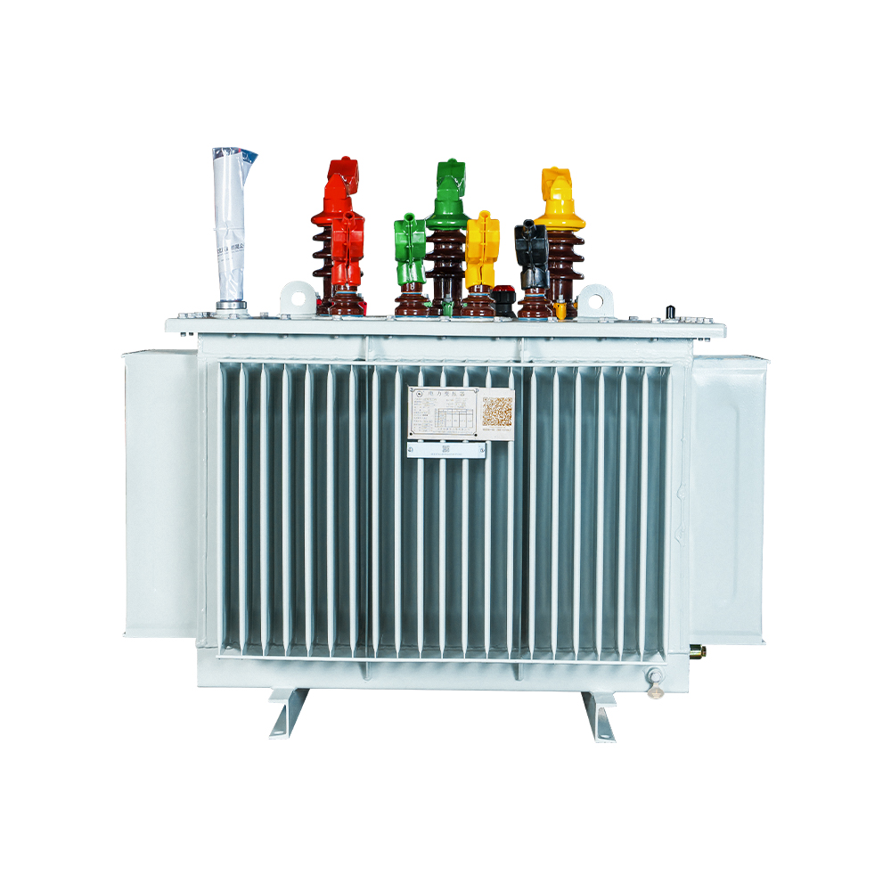
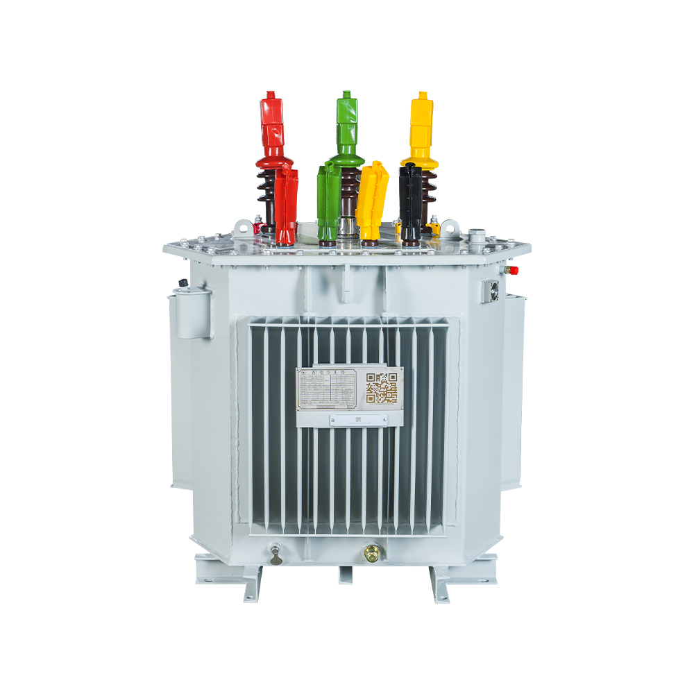
(1) Oil-Immersed Transformers (Mineral Oil)
The most common transformer type, using mineral oil for both insulation and cooling. Advantages include excellent electrical insulation properties, high heat capacity, self-healing properties (oil fills gaps), and relatively low cost. Typical applications include grid transformers, large industrial transformers, and distribution substations.
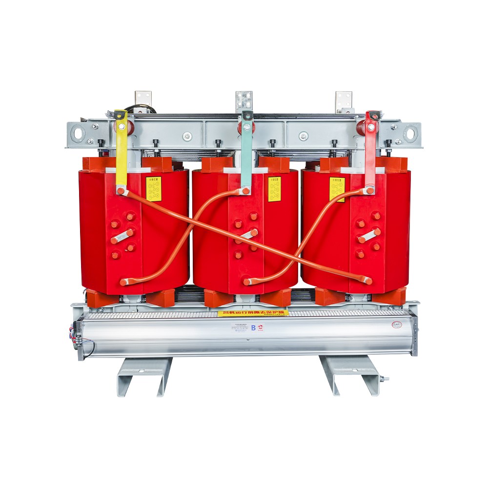
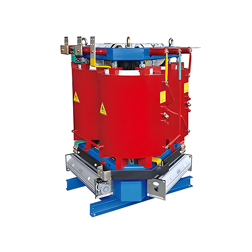
(2) Dry-Type Transformers (Air-Cooled or Resin Cast)
Insulated with air or solid resin materials, eliminating fire hazard and environmental contamination risks associated with oil. Types include:
- VPI (Vacuum Pressure Impregnated): Windings impregnated with polyester or epoxy resin under vacuum-pressure
- Cast Resin (CR): Windings encapsulated in solid epoxy resin, providing excellent mechanical and moisture protection
- Open Ventilated (OV): Natural air convection cooling with exposed windings
Dry-type transformers are preferred indoors, in fire-sensitive locations, and where environmental regulations limit oil usage.
(3) Ester Oil Transformers (Natural and Synthetic Esters)
Increasingly popular as a more environmentally friendly alternative to mineral oil. Ester oils have higher flash and fire points (higher fire safety), are biodegradable, and have greater moisture tolerance. They are widely used in environmentally sensitive locations, buildings, and offshore installations.
(4) Gas-Insulated Transformers (GITs)
Using SF6 gas for insulation, providing a compact, fire-safe solution for special applications. Typically used in urban substations, high-voltage applications, and offshore installations where space is limited.
3.2 By Application and Voltage Level
(1) Generator Step-Up Transformers (GSUs)
Located at power generation facilities to step-up generator voltage to transmission levels (typically 10-25 kV primary to 115-765 kV secondary). High capacities (100 MVA to 1,500+ MVA), high reliability, and low losses are essential.
(2) Power Transformers (Grid and Transmission)
Used in transmission networks for voltage transformation at substations. Typical ratings range from 50 MVA to 1,000+ MVA with voltage classes up to 1,100 kV. They are characterized by high efficiency, robust design, and advanced cooling systems.
(3) Distribution Transformers
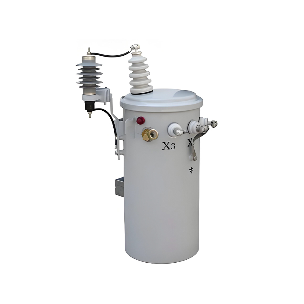
Used to step-down medium voltage (11-33 kV) to low voltage (400 V or 230 V) for final distribution to consumers. Ratings typically range from 5 kVA to 10 MVA. Distribution transformers are often pole-mounted or pad-mounted for outdoor installation. They are designed for high efficiency over a range of loading conditions, with some designs optimized for low-load scenarios.
(4) Converter Transformers (HVDC and Industrial Drives)
Special transformers designed for power electronics applications. Key features include special winding configurations, harmonic control capability, and design for non-sinusoidal voltage and current waveforms.
(5) Earthing/Off-Circuit Tap-Changing Transformers
Application-specific transformers with limited voltage variation capability, typically through off-circuit (de-energized) tap changers.
(6) Special Purpose Transformers
Including furnace transformers (high current, low voltage), welding transformers, and rectifier transformers for electrochemical processes.
Transformer Classification by Application
| Application Type | Typical Rating (MVA) | Voltage Classes | Primary Cooling | Key Characteristics |
|---|---|---|---|---|
| Generator Step-Up | 100 – 1,500+ | 10-25 kV / 115-765 kV | ONAN, ONAF, OFAF | High efficiency, reliability, low losses |
| Power/Transmission | 50 – 1,000+ | 50-765 kV / other | ONAN, OFAF, ODAF | Efficiency, voltage control with OLTC |
| Distribution (Substation) | 5 – 50 | 11-33 kV / 0.4-3.3 kV | ONAN | Cost-effective, standard designs |
| Distribution (Pole-Mounted) | 5 – 500 kVA | 11 kV / 0.4 kV | ONAN | Compact, light, outdoor environment |
| HVDC Converter | 100 – 1,000+ | Special design | ONAN/OFAF | Harmonic control, valve side insulation |
3.3 By Core Construction
(1) Core-Type Transformers
Windings surround the core limbs. This construction offers improved cooling due to better winding surface access, reduced leakage flux, and improved mechanical strength. Core-type designs are widely used for high-voltage, high-power applications where electrical performance and cooling are critical.
(2) Shell-Type Transformers
Core surrounds the windings (core encloses the winding). This design provides better short-circuit withstand capability, lower leakage flux, and higher mechanical strength. Shell-type transformers are used for demanding applications such as generator step-up, HVDC converter transformers, and high-current, low-voltage transformers.
(3) Amorphous Metal Core Transformers
Core constructed from amorphous metal (non-crystalline) alloys, with losses approximately 70% lower than conventional silicon steel cores. These transformers achieve higher efficiency, especially at low load conditions, but are more expensive and have lower saturation flux density. They are widely used in distribution networks to meet energy efficiency regulations (e.g., USA DOE 2016 standards).
(4) Wound Core Transformers
Core is constructed from continuous strip of silicon steel wound into a spiral and then cut and assembled. This design offers lower flux leakage, reduced core losses, and improved mechanical stability. Wound core transformers are used in distribution applications where efficiency and compactness are required.
3.4 By Winding Configuration
(1) Two-Winding Transformers
The most common design, with one primary and one secondary winding. All power is transferred through electromagnetic induction between these two windings. Transformer ratio may be adjustable through tap changers.
(2) Auto-Transformers
A single winding with a tap, acting as both primary and secondary. Auto-transformers are smaller, lighter, and more efficient than two-winding transformers for the same rated power. They are commonly used for voltage ratios up to 2:1 and in HVDC converter applications. However, they do not provide electrical isolation between primary and secondary circuits.
(3) Multi-Winding Transformers
Transformers with more than one secondary winding, or multiple primary windings, allowing connection to multiple voltage levels or power supplies. Applications include substation transformers supplying multiple voltage levels or rectifier transformers with several secondary windings for HVDC converters.
4. Key Design Parameters and Performance Specifications
4.1 Rated Power (kVA or MVA)
The apparent power a transformer can deliver continuously under specified conditions. Selection must consider both the base load and peak demand, with appropriate overload capacity for emergency conditions. Transformer ratings are standardized per IEC 60076 and IEEE C57.12 standards.
4.2 Voltage Ratio and Tap Changer
The turns ratio determines the voltage transformation. Off-circuit (de-energized) or on-load tap changers (OLTC) adjust the ratio to maintain secondary voltage within specified limits as primary voltage and load vary. Tap changer selection influences transformer cost, size, and maintenance requirements.
4.3 Impedance Voltage (Percentage Impedance)
The voltage drop across the transformer at rated current expressed as a percentage of rated voltage. Impedance determines the short-circuit current level and the transformer's ability to limit fault currents. Typical values range from 4% to 12%, with higher impedance used where fault current limitation is required. Impedance affects voltage regulation and must be coordinated with network protection.
4.4 Efficiency and Losses
Transformer losses consist of two components:
- No-load losses (core losses): Losses in the core material due to hysteresis and eddy currents, essentially constant regardless of load. These determine the transformer's efficiency at low loads and are therefore critical for distribution transformers with typical part-load operation. Materials with lower losses include amorphous metals and high-grade grain-oriented silicon steel.
- Load losses (copper losses): Losses in windings due to I²R heating, proportional to the square of the load current. These determine the transformer's efficiency at high loads and at rated capacity. Lower load losses are achieved through larger conductor sections and improved winding design.
4.5 Voltage Regulation
The change in secondary voltage as the load varies from no-load to full-load at a given power factor. Good regulation (low voltage drop) is essential for sensitive loads and precise equipment operation.
4.6 Winding Connection and Vector Group
Specifies the connection type (delta, star, or zigzag) and the phase displacement between primary and secondary. The vector group must match system requirements and facilitate parallel operation of multiple transformers.
4.7 Insulation Class and Temperature Rise Limits
Transformers are classified by insulation class (Class A, B, F, H) and temperature rise limits. Typically, Class A (105°C) insulation has a 65°C temperature rise above ambient under continuous operation. The insulation must withstand thermal, mechanical, and electrical stresses during normal operation and faults.
4.8 Short-Circuit Strength
A transformer must withstand short-circuit forces without damage. This is specified by the short-circuit current and duration (typically 0.5 to 3 seconds). The windings and core must be designed to resist the electromagnetic forces that occur during a fault.
4.9 Efficiency Classes and Standards
IEC and IEEE define efficiency classes for transformers to support energy efficiency goals. Examples include:
- IEC 60076-20: Defines efficiency classes for transformers, with Class 1 (High) and Class 2 (Ultra High) efficiency levels
- US DOE Efficiency Standard (10 CFR Part 431): Prescribes minimum efficiency values for distribution transformers
- EU Ecodesign Directive (EU 548/2014) Tier 2: Defines high-efficiency standards for transformers used in the European Union
- India BEE Star Rating: Implements a star rating system for distribution transformers based on efficiency levels
4.10 Performance Comparison by Core Material
| Core Material | No-Load Loss Reduction | Advantages | Limitations | Typical Applications |
|---|---|---|---|---|
| Silicon Steel (Grain-Oriented) | Baseline | Cost-effective, well-established technology, robust | Losses higher than new materials | All transformer types, standard designs |
| High-Performance Silicon Steel | 10-20% reduction | Improved efficiency, moderate cost | Higher cost, availability | High-efficiency distribution transformers |
| Amorphous Metal | 70-80% reduction | Excellent efficiency, especially at low loads | Higher cost, limited availability, lower saturation flux density | Distribution transformers for energy efficiency |
5. Construction and Key Components
5.1 Core Construction
The magnetic core of a three-phase transformer is the path for the magnetic flux and must be designed to minimize losses while maintaining mechanical integrity. Core design influences losses, noise, and short-circuit capability.
Core materials include silicon steel laminations (0.23-0.35 mm thick), grain-oriented silicon steel, and amorphous alloys. The laminations are electrically insulated to reduce eddy current losses. The core is constructed with butt or miter joints to minimize the air gap and reduce losses.
5.2 Winding Construction
Windings conduct the electrical energy. Winding design must meet current-carrying, insulation, and thermal requirements. The primary and secondary windings may be located concentrically (cylindrical) or interleaved (sandwich), depending on the transformer design. Concentric windings are simpler and more common, while interleaved windings reduce leakage flux and improve short-circuit performance.
Winding materials are typically copper for its excellent conductivity, or aluminum for lower cost and weight (though aluminum windings require larger conductor sizes). Windings may be round, rectangular, or foil-wound (for low-voltage, high-current applications). Insulation between windings is provided by paper, enamel coating, or resin.
5.3 Insulation System
Transformer insulation is classified by thermal class (A, B, F, H). The insulation must withstand the electrical stress, withstand the operating temperature, and maintain mechanical stability over the transformer's service life (typically 30-50 years for power transformers, 20-40 years for distribution transformers).
Solid insulation includes paper, pressboard, and resin. Liquid insulation (mineral oil, ester oils, or synthetic liquids) provides electrical insulation and cooling. Gases such as SF6 or dry air are used in special applications.
5.4 Cooling System
Cooling is essential for reliable transformer operation as losses generate heat. Cooling methods include natural and forced convection. The classification is indicated by the transformer's cooling code:
- ONAN: Oil Natural, Air Natural (self-cooled, no fans or pumps)
- ONAF: Oil Natural, Air Forced (natural oil circulation with forced air cooling via fans)
- OFAF: Oil Forced, Air Forced (forced oil circulation with radiators cooled by forced air)
- ODAF: Oil Directed, Air Forced (directed oil flow through windings, forced air cooling)
5.5 Tap Changer
The tap changer allows adjustment of the turns ratio to compensate for voltage variations in the power system. It consists of a selector switch and a change-over switch. On-load tap changers (OLTC) can change taps while the transformer is energized, whereas off-circuit (de-energized) tap changers require the transformer to be de-energized.
5.6 Bushings and Terminals
Bushings are insulated devices that allow electrical connection to the transformer windings. The bushing type depends on the voltage level, with porcelain or composite bushings for high-voltage applications. Terminal arrangements vary by application, with multiple connections for different voltage levels.
5.7 Protective Devices and Monitoring
Transformers are equipped with various protective devices and monitoring systems:
- Buchholz relay: Detects gas and oil flow in oil-filled transformers, indicating internal arcing or insulation failure
- Pressure relief valve: Releases pressure during fault conditions to prevent tank rupture
- Temperature indicators: Measure winding temperature and oil temperature for thermal monitoring
- Oil level indicator: Monitors oil level and warns of leaks
- Dissolved gas analysis (DGA): Key diagnostic tool for oil-filled transformers, identifying faults from gas concentrations
- Moisture-in-oil monitoring: Monitors water content in oil for insulation health assessment
6. Selection Criteria and Application Guidelines
6.1 Key Selection Factors
Selecting the appropriate three-phase transformer requires a thorough assessment of the application:
- Power rating: The kVA or MVA rating required, based on load demand and future expansion
- Voltage levels: Primary and secondary voltages, including tap changer voltage range
- Frequency: Typically 50 Hz or 60 Hz, depending on regional grid standards
- Cooling method: ONAN, ONAF, OFAF, ODAF, or dry-type, based on environmental and space constraints
- Installation environment: Indoor, outdoor, marine, desert, or arctic conditions, including temperature, humidity, and exposure to contaminants
- Efficiency requirements: Efficiency class and loss limits required by regulations (DOE, Ecodesign, etc.)
- Budget and lifecycle cost: Initial cost versus efficiency, maintenance, and energy cost considerations
- Regulatory compliance: Standards (IEC, IEEE, local regulations), environmental requirements, and site approvals
6.2 Application-Specific Recommendations
Distribution Substations
Distribution transformers are typically located in substations, on poles, or on pads. Oil-immersed transformers are standard, with ratings from 5 kVA to 5 MVA. Dry-type transformers are used indoors or where fire hazards are a concern. For high-efficiency applications, amorphous metal core transformers are recommended.
Industrial Facilities
Industrial transformers supply power to motors, drives, furnaces, and other equipment. They often have high short-circuit withstand capability, high efficiency, and reliable operation. Dry-type transformers are common indoors, while oil-immersed transformers are used outdoors.
Renewable Energy Systems
Solar inverters and wind turbine converters require step-up transformers. These applications involve bidirectional power flow, frequent load cycling, and variable power output. Special transformer designs include low-loss core materials and enhanced cooling for intermittent operation.
Urban and Building Applications
Cast-resin dry-type transformers are preferred for indoor installations due to fire safety and environmental concerns. Compact and quiet transformers are required for urban installations where space and noise constraints are significant.
6.3 Efficiency and Lifecycle Cost Considerations
For long-term cost-effectiveness, consider:
- No-load losses: The cost of core losses over the transformer life; significant for transformers operating at low loads for extended periods
- Load losses: The cost of copper losses, proportional to load and hours of operation
- Capital cost: The initial purchase price and installation cost
- Maintenance cost: Inspection, oil testing, and repair costs over the transformer life
6.4 Failure Prevention and Reliability Considerations
Transformer failures can be catastrophic and expensive. Important considerations include:
- Short-circuit capability: Ensuring the transformer can withstand system faults without damage
- Overload capability: The ability to handle temporary overloads without exceeding temperature limits
- Protection and coordination: Reliable protection devices and coordination with system protection schemes
- Condition monitoring: Dissolved gas analysis (DGA), temperature monitoring, and electrical testing to detect incipient failures
7. Emerging Technologies and Future Trends
7.1 Digital and Smart Transformers
The integration of sensors, communication, and data analytics is transforming transformer design:
- Condition monitoring: Real-time monitoring of temperature, gases, moisture, partial discharge, and vibration
- Predictive maintenance: Algorithms and AI to predict failure and schedule maintenance
- Remote monitoring and control: Real-time data transmission to control centers for improved grid visibility
- Smart grid integration: IoT connectivity and data exchange for grid optimization
7.2 Amorphous Metal Core Transformers
Amorphous metal cores reduce no-load losses by 70-80% compared to conventional steel. However, these cores are more expensive and have lower saturation flux density. For distribution transformers, the trade-off between efficiency and cost is favorable, especially where energy costs are high or load factors are low.
7.3 Eco-Friendly Insulation and Cooling Media
The industry is moving toward sustainable transformer insulation:
- Natural ester oils: Vegetable-based oils with high fire point, biodegradable, and environmentally safe
- Synthetic esters: High-performance alternatives with excellent electrical and thermal properties
- Dry-type transformers: Eliminating oil for environmental and fire safety reasons
- Gas-insulated transformers: Using SF6 or dry air for compact and safe designs
7.4 High-Temperature Superconducting Transformers
Superconducting transformers use high-temperature superconducting (HTS) windings to achieve zero resistance, eliminating copper losses. Although currently limited to research and specialized applications, HTS technology promises extremely high efficiency and compact designs for future transmission and distribution systems.
7.5 Grid Integration of Renewable and Distributed Energy
Transformers are evolving to handle:
- Bi-directional power flow: From solar and wind farms back to the grid, requiring transformers that can accommodate power flow in both directions without compromising performance
- Voltage fluctuations: Variable output from renewable sources affecting grid voltage, requiring improved tap changer performance
- Harmonics and power quality: Inverters and converters introduce harmonics, requiring transformers with harmonic mitigation capability
- Energy storage integration: Transformers for battery storage systems with fast response, high cyclic life, and bidirectional power capability
8. Conclusion
Three-phase power transformers are fundamental components of modern electrical infrastructure, enabling efficient generation, transmission, and distribution of electricity. Understanding the principles, classification, construction, and selection criteria is essential for power system professionals.
Key takeaways from this article include:
- Fundamental principles: Faraday's Law governs transformer operation, with voltage ratio determined by turns ratio, and power conserved (neglecting losses).
- Classification: Transformers are classified by cooling medium, application, core construction, and winding configuration. Selection depends on the specific application requirements.
- Design parameters: Efficiency, voltage regulation, insulation class, and short-circuit strength are critical parameters that influence transformer selection.
- Emerging technologies: Digital transformers, amorphous metals, ester oils, and superconducting windings are driving innovation in transformer design for improved efficiency, reliability, and environmental performance.
As power systems evolve with renewable energy integration, digitalization, and sustainability goals, the demand for advanced transformer solutions will continue to grow. Power system professionals must stay informed about these developments to ensure reliable, efficient, and environmentally responsible transformer selection and operation.
Appendix: Key Standards and Specifications
| Standard | Title/Scope | Key Requirements |
|---|---|---|
| IEC 60076 | Power Transformer Standards (multiple parts) | Rating, testing, construction, and performance |
| IEEE C57.12 | Standard for Transformers (multiple parts) | Testing, application, and construction |
| IEC 60076-20 | Efficiency Classes for Transformers | Class 1 (High) and Class 2 (Ultra High) efficiency |
| US DOE 10 CFR Part 431 | Distribution Transformer Efficiency Standards | Minimum efficiency values for low-voltage dry-type and medium-voltage transformers |
| EU Ecodesign (EU 548/2014) | Transformer Efficiency Requirements | Tier 1 and Tier 2 efficiency levels for transformers |
| IEC 60076-1 | General Requirements for Power Transformers | Definitions, ratings, and construction |
| IEEE C57.91 | Guide for Loading Power Transformers | Loading guidelines, temperature limits, and failure modes |
| IEC 60076-2 | Temperature Rise Test for Transformers | Temperature rise limits and test methods |
Recommended Products

 Contact

Contact
-

wxj.810@163.com
-

+86-523-82962116
-

No. 111, Guoqing East Road, Chengdong High-tech Industrial Park, Taixing City, Jiangsu Province, China
Copyright © 2026 by Jiangsu Hengyuan Transformer Co., Ltd. Rights Reserved.
