 English
 русский
 Español
 عربى
Three Phase Transformer Guide: Configurations, Core Types, and Selection
Content
- 1 What Is a Three Phase Transformer and How Does It Work?
- 2 Delta vs. Wye: How Three Phase Transformer Connections Work
- 3 Oil-Filled or Dry-Type: Matching the Unit to the Site
- 4 Losses and Efficiency: What a Three Phase Transformer Costs in 20 Years
- 5 How to Select the Right Unit in Five Steps
- 6 Frequently Asked Questions
A 630 kVA three phase transformer with an amorphous alloy core draws roughly one quarter of the no-load power of a silicon-steel unit of the same rating. For a substation that stays energised 8,760 hours a year, that gap can repay the price premium within five years. No-load loss is only one of several specifications that decide whether a unit fits its site, duty cycle, and protection scheme. This guide presents those engineering decisions in the order they appear on a procurement sheet.
What Is a Three Phase Transformer and How Does It Work?
A three phase transformer is a static electromagnetic unit that steps voltage up or down between two three-phase AC systems without changing frequency.
Three-phase power uses three alternating voltages displaced by 120 degrees. Because the waveforms overlap, power flow is continuous, which is why three-phase systems deliver more power with smaller conductors and lighter machines than single-phase systems.
A three phase transformer supports that system with three winding pairs on a common core, normally a three-limb core with both windings of each phase placed concentrically on its own limb.
Integration saves material. A 1,000 kVA three-phase unit uses 15 to 20 percent less core steel and copper than three single-phase units of the same capacity, with a smaller footprint and foundation.
Three-phase systems dominate generation and distribution for three reasons:
- Constant power, which removes torque pulsation in motors and rectifiers.
- About 73 percent more power per conductor for the same line current.
- Smaller transformers, generators, and motors for the same output.
For the equations behind turns ratio and impedance, the article on three phase transformer engineering principles explains how nameplate figures are derived.
Delta vs. Wye: How Three Phase Transformer Connections Work
Delta and wye describe how the three windings on each side of a three phase transformer are joined; the combination fixes the phase shift, the availability of a neutral, and behaviour under unbalanced loads.
In delta, each winding end connects to the next start, forming a closed triangle. In wye, one end of each winding meets at a common neutral point and the other three ends form the line terminals. The four standard groups pair one primary with one secondary connection.
| Connection | Phase shift | Neutral available | Primary use |
| Delta-Delta | 0 degrees | No | Industrial high-current loads |
| Delta-Wye (Dyn11) | +30 degrees | Yes, on secondary | Distribution, 10 kV to 0.4 kV |
| Wye-Delta | -30 degrees | Yes, on primary | Step-down at large plant entrances |
| Wye-Wye | 0 degrees | Yes, both sides | Utilities, with a delta stabilising winding |
Choose delta when
You need robustness under unbalanced or faulted loads, no neutral is required, and magnetising distortion must stay low. Delta-delta survives a failed phase in an open-delta reduced-capacity mode.
Choose wye when
You must feed single-phase loads between phase and neutral, or protection needs a grounding reference and a stable star point for earthing.
Oil-Filled or Dry-Type: Matching the Unit to the Site
The insulation and cooling medium determines where a three phase transformer can be installed, how heat is removed, and which fire-protection and containment measures the building needs.
Oil-filled units use mineral oil or biodegradable ester to insulate the windings and transfer heat to the tank. They remain the most cost-effective choice above roughly 315 kVA and perform best outdoors. Modern ester fluids raise the flash point above 300 degC and ease environmental compliance.
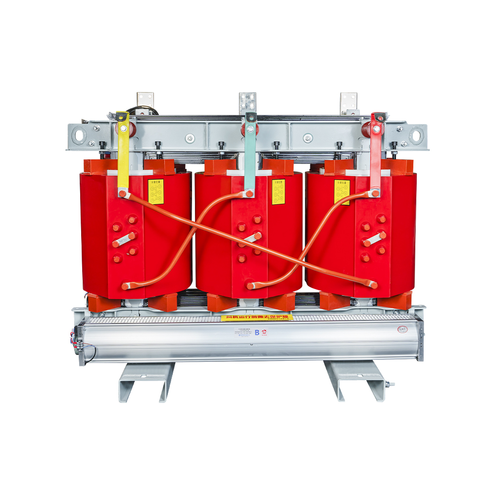
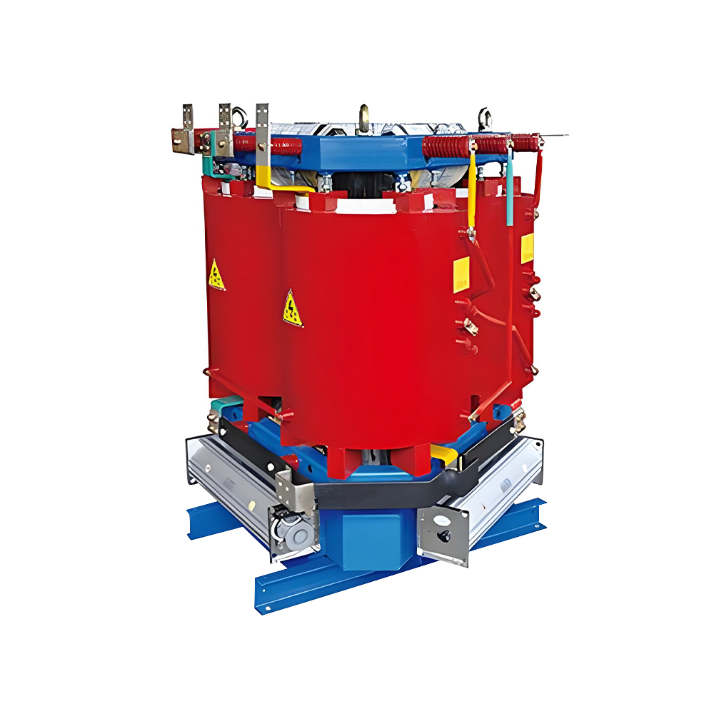
Dry-type transformers, usually cast in epoxy resin, operate indoors without oil, remove the containment pit, and cut the building fire load. First cost per kVA is higher, and windings need an IP2X or higher enclosure against dust and condensation.
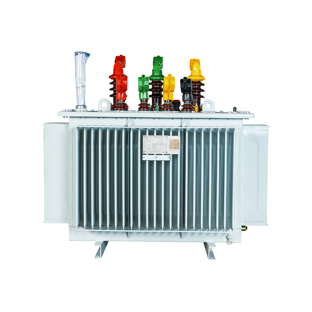
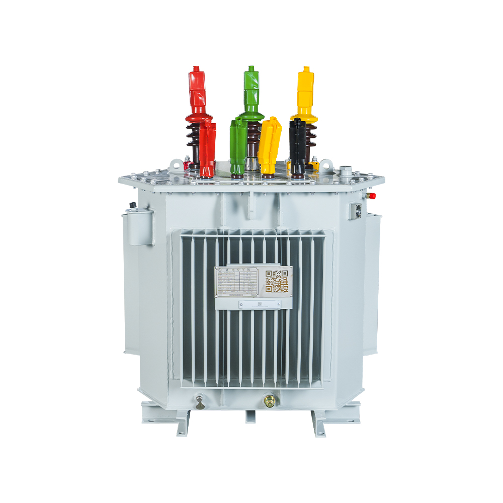
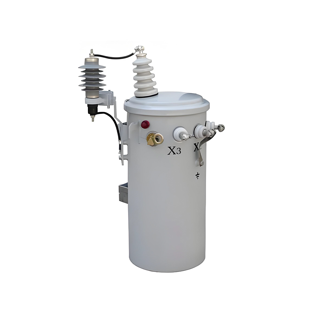
For distribution projects in this class, Jiangsu Hengyuan Transformer Co., Ltd. supplies oil-immersed and dry-type three phase transformers with silicon steel or amorphous alloy cores: an amorphous alloy oil-immersed unit, a silicon-steel oil-immersed unit, and an amorphous alloy dry-type unit.
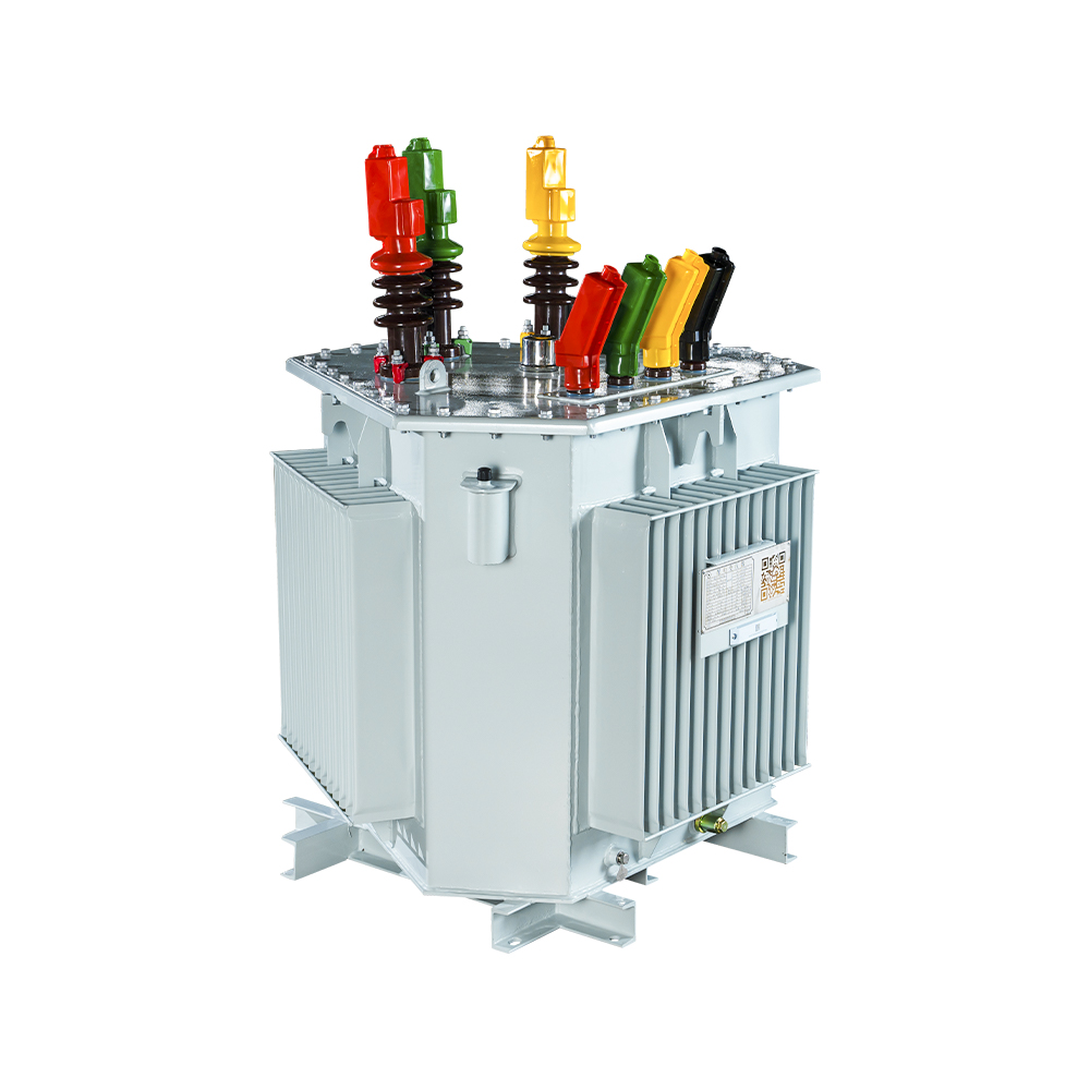 Amorphous Alloy Core Oil-immersed Transformer for Low Loss DistributionThis oil-immersed unit uses amorphous alloy core material to minimize no-load losses, directly addressing the lifetime operating cost concern raised after the card. It suits distribution projects needing high efficiency and reliability.View Product →
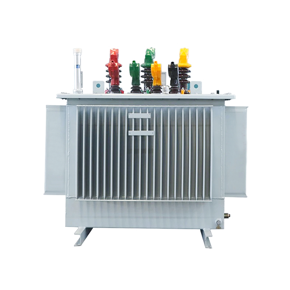 Silicon Steel Core Oil-immersed Transformer with Low No-load Loss DesignAs a leading oil-immersed option, this transformer combines high-performance silicon steel and an optimized coil structure to reduce no-load losses. It offers sealed construction and low maintenance for cost-effective continuous operation.View Product →
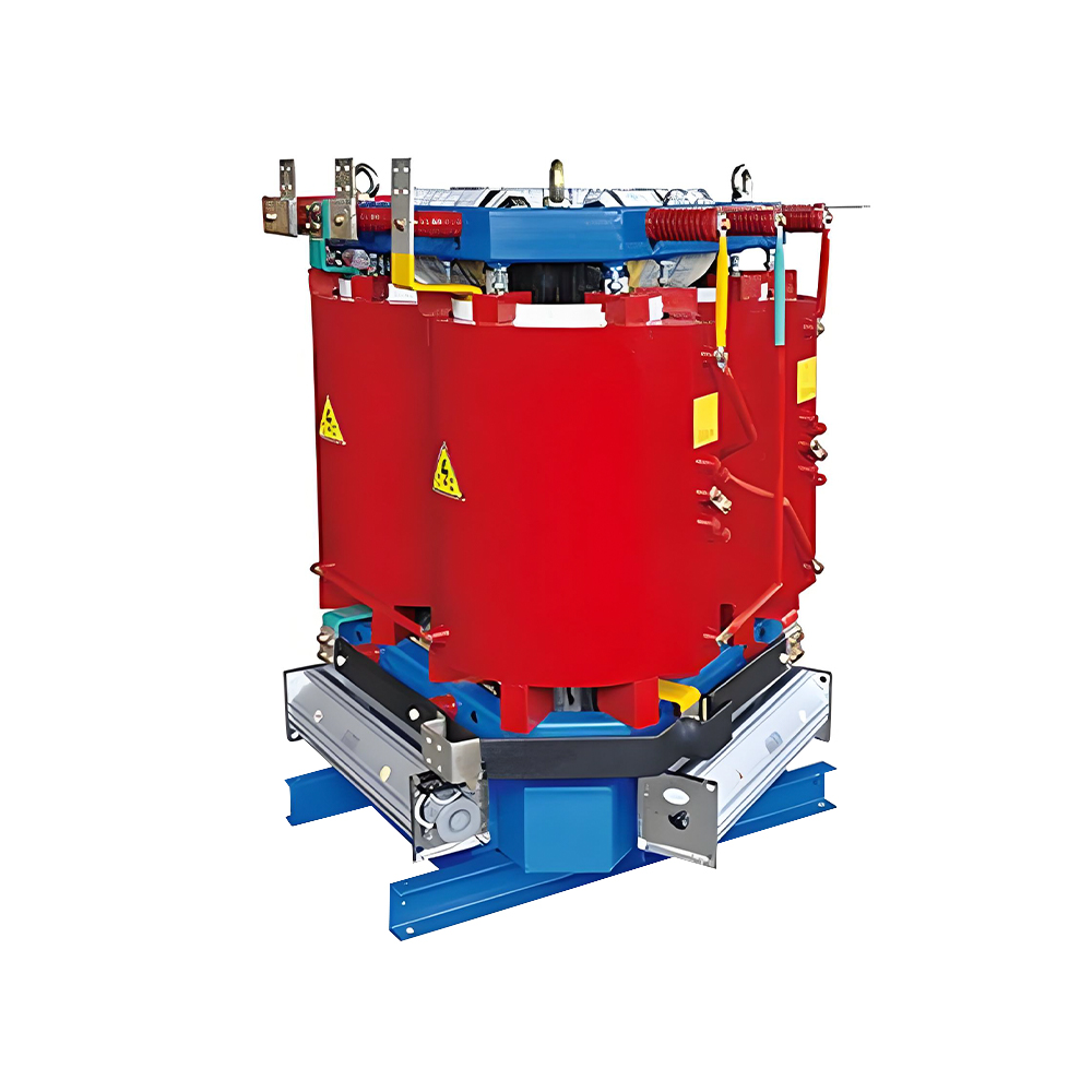 Amorphous Alloy Core Dry-type Transformer for Safe and Efficient Indoor UseThis dry-type transformer with an amorphous alloy core delivers ultra-low no-load losses and oil-free, fire-safe operation. It is a strong choice where indoor constraints or environmental concerns make oil-filled units impractical.View Product →
Losses and Efficiency: What a Three Phase Transformer Costs in 20 Years
No-load losses run at full value 24 hours a day regardless of load, so core material is the strongest driver of a three phase transformer's lifetime operating cost.
No-load loss, or core loss, is energy dissipated by hysteresis and eddy currents whenever the transformer is energised. Load loss, or copper loss, grows with the square of the current. Distribution transformers sit below nameplate rating for most of their life, so core loss often dominates annual energy loss.
Amorphous alloy cores remove the crystalline grain structure of silicon steel, cutting hysteresis loss sharply. Type-test reports on 1,000 kVA units show no-load losses 60 to 80 percent lower than conventional grain-oriented silicon steel.
How to Select the Right Unit in Five Steps
Specifying a three phase transformer correctly comes down to five verifications: service voltage, kVA, vector group, impedance, and cooling class.
Work through the steps in order. Skipping any one causes a failed factory acceptance test, an incompatible protection setting, or a premature overload.
Confirm the service voltages
Record primary and secondary line-to-line voltages and identify the earthing system on each side. A 10 kV to 0.4 kV project normally leads to a Dyn11 vector group.
Calculate the kVA rating
Sum the connected loads, apply a demand factor of 0.6 to 0.8 for mixed industrial loads, add margin for expansion, and round up to the nearest standard rating: 100, 160, 250, 400, 630, 800, or 1,000 kVA.
Specify the vector group
Match the group to the grounding and protection philosophy. Dyn11 is the safe default for 10/0.4 kV distribution because it provides a stable secondary neutral.
Check the impedance voltage
Impedance (Uk%) sets the short-circuit current and voltage regulation. A typical 4 to 6 percent impedance is usual for distribution; higher values protect equipment but increase voltage drop.
Select the cooling class
Choose ONAN for outdoor installations or AN/AF for indoor units with intermittent higher loading. Verify altitude and ambient temperature limits in the data sheet.
For a direct comparison of standard ratings and dimensions, review the three phase transformer range in the 6 to 35 kV product catalogue.
Frequently Asked Questions
Short, decision-ready answers to the questions procurement engineers ask most often.
What is the difference between a single-phase transformer and a three phase transformer?
A single-phase transformer has one primary and one secondary winding and delivers pulsating power. A three phase transformer has three winding pairs on a shared core, delivers constant power, and serves three-phase loads with less material per kVA.
Can three single-phase transformers replace one three phase transformer?
Yes, three single-phase units can be banked into a three-phase group. That gives spare-unit flexibility, but costs 15 to 25 percent more in material, occupies more space, and runs slightly less efficiently.
What does Dyn11 mean on a three phase transformer nameplate?
D means the high-voltage winding is delta connected, y means wye connected, n means the low-voltage neutral is brought out, and 11 means a 30 degree phase shift, with the low-voltage side leading by the clock position 11.
How do I estimate the kVA rating my facility needs?
Sum the full-load power of connected loads, apply a demand factor of 0.6 to 0.8, add margin for expansion, and round up to the nearest standard rating. For motor loads, verify the starting current and the voltage drop at start.

 Contact

Contact
-

wxj.810@163.com
-

+86-523-82962116
-

No. 111, Guoqing East Road, Chengdong High-tech Industrial Park, Taixing City, Jiangsu Province, China
Copyright © 2026 by Jiangsu Hengyuan Transformer Co., Ltd. Rights Reserved.
