 English
 русский
 Español
 عربى
3 Phase Electric Transformer: How to Specify Winding, Cooling, and Sizing
Content
- 1 What Is a 3 Phase Electric Transformer?
- 2 Delta vs. Wye: Choose the Winding That Matches the Network
- 3 Dry-Type vs. Oil-Immersed: Match the Construction to the Building
- 4 How to Size a 3 Phase Electric Transformer Correctly
- 5 Where the Transformer Sits in the Distribution Chain
- 6 Frequently Asked Questions About 3 Phase Electric Transformers
A 250 kW conveyor line being installed in a food processing plant requires its own step-down point. The facility receives primary power at 10 kV, while motors, variable-frequency drives and control cabinets run on 400 V three-phase. The engineer writing the specification must settle four questions before any purchase order is placed: winding configuration, insulation medium, impedance, and cooling class. A 3 phase electric transformer is not an interchangeable commodity. Each decision changes efficiency, footprint, floor loading, protection coordination and maintenance frequency for the next two decades of service.
What Is a 3 Phase Electric Transformer?
A 3 phase electric transformer is a static electromagnetic device that transfers three-phase AC power between circuits at different voltage levels using three sets of windings coupled through a shared magnetic core.
Three primary windings and three secondary windings are wound on a laminated steel core with three limbs. Alternating current in the primary windings creates magnetic flux that links all three secondary windings by induction, producing a secondary voltage proportional to the turns ratio. Because the transformer has no moving parts, its service life is governed by insulation temperature, winding stress and load cycles rather than mechanical wear.
Three-phase power matters because the three voltages are displaced by 120 electrical degrees. A balanced three-phase load therefore receives constant instantaneous power, whereas single-phase power pulsates at twice line frequency. This is why a three-phase transformer of a given kVA rating is roughly 15-20 percent lighter and less expensive than three single-phase units with the same total rating, and why industrial networks use three-phase equipment almost exclusively.
Delta vs. Wye: Choose the Winding That Matches the Network
The winding connection dictates whether the transformer can supply line-to-neutral loads, how it responds to unbalanced current, and what phase shift is introduced between primary and secondary. This decision is made once, at specification time, and it cannot be corrected afterward by panel adjustments.
A delta connection links each winding between two phase conductors. It has no neutral, so it cannot feed single-phase loads directly, but the closed loop inside the delta rebalances flux and tolerates unbalanced phase currents well. A wye connection joins one end of each winding at a common neutral. It provides the neutral needed for mixed lighting and power loads at 230/400 V, and it can be solidly grounded or impedance grounded for fault management.
Distribution practice in most markets favors a delta primary with a wye secondary. The delta primary blocks triplen harmonic currents from entering the utility network, and the grounded wye secondary keeps line-to-ground voltages bounded under fault conditions.
| Configuration | Neutral Available | Phase Shift | Typical Application | Main Risk |
| Delta-Delta | None | 0 degrees | Balanced industrial loads, isolated networks | No grounding reference; ferroresonance in cable-fed systems |
| Delta-Wye | Secondary | 30 degrees | Standard distribution step-down | Paralleling requires matched vector groups |
| Wye-Delta | Primary | 30 degrees | Generator step-up | Secondary must be grounded downstream |
| Wye-Wye | Both | 0 degrees | Rare | Third-harmonic distortion without a delta tertiary winding |
Manufacturers identify these arrangements with vector group codes. The most common distribution code is Dyn11: D is a delta-connected primary, y is a wye-connected secondary, n means the neutral is brought out to a terminal, and 11 means the secondary line-to-neutral voltage lags the primary by 30 degrees.
Dry-Type vs. Oil-Immersed: Match the Construction to the Building
The insulation and cooling medium decides where the transformer may be installed, what fire protection and containment the building must provide, and how much short-term overload headroom the unit carries.
Oil-Immersed Construction
- Best overall efficiency above 500 kVA
- High short-term overload capacity
- Outdoor installation typical
- Needs fire barrier and oil containment
- Annual oil sampling recommended
Dry-Type Construction
- Safe for indoor and enclosed spaces
- No oil containment or fire suppression
- Higher first cost per kVA
- Sensitive to dust and humidity
- Simpler long-term maintenance
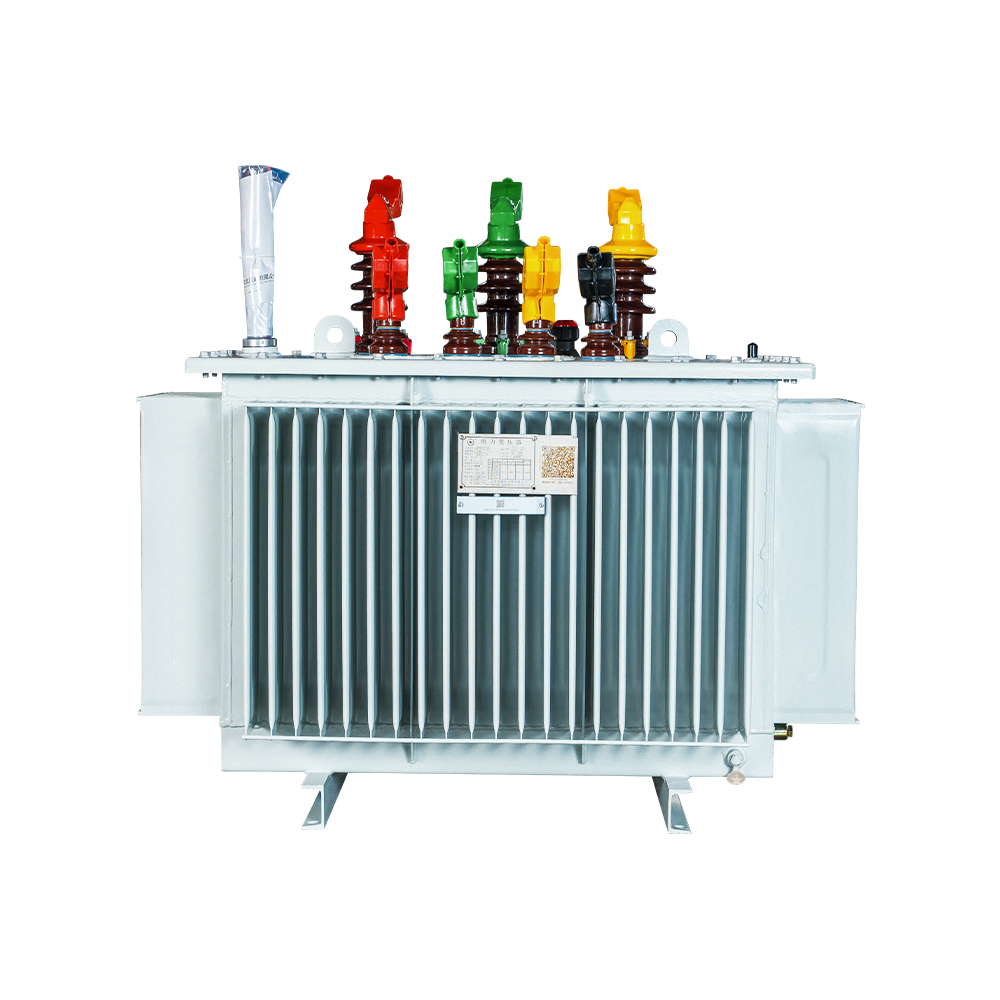
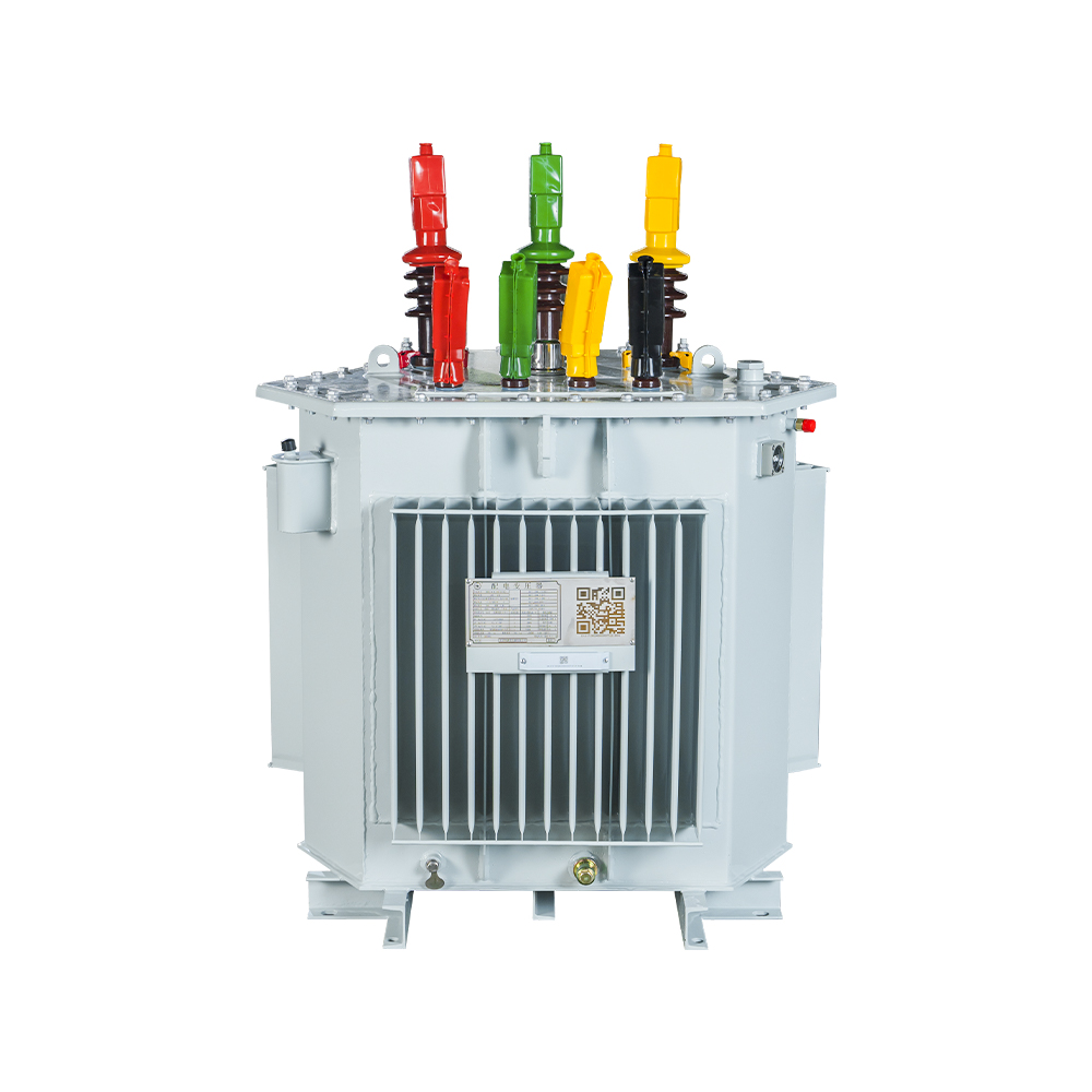
Oil-immersed transformers use paper insulation and mineral or ester oil for cooling, typically with ONAN circulation. The oil mass absorbs heat during overload peaks, which is why oil units can carry roughly 150-200 percent of nameplate rating for short intervals. They are more economical above approximately 500 kVA and are the standard choice for outdoor substations.
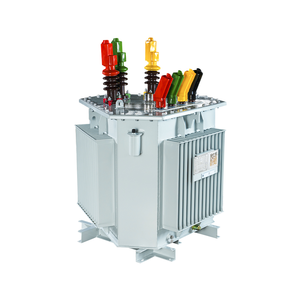 Amorphous Alloy Core Oil-immersed Transformer for Energy EfficiencyThis oil-immersed unit suits outdoor substations needing high overload capacity. Its amorphous core cuts no-load losses sharply, reducing energy costs and emissions while offering strong short-circuit withstand and low noise.View Product →
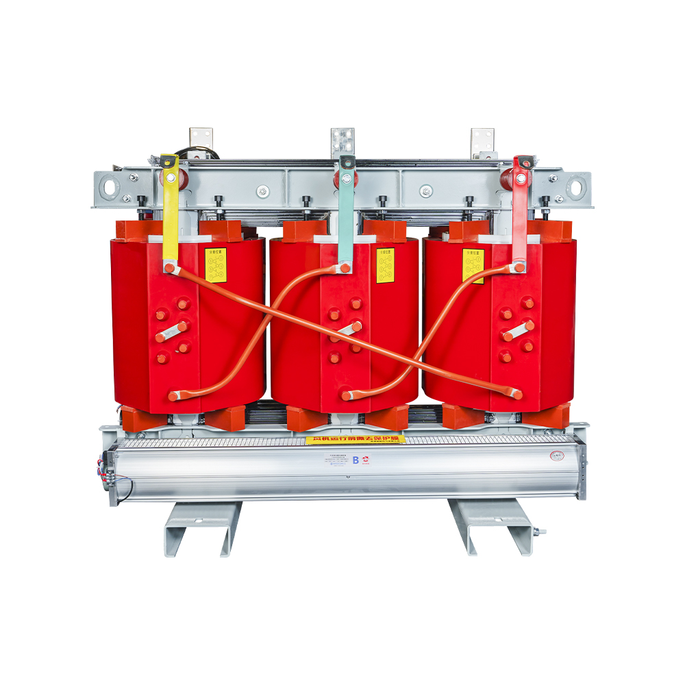
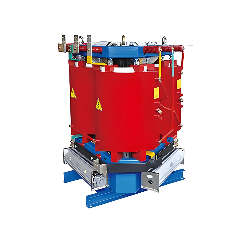
Dry-type transformers use cast resin or vacuum-pressure-impregnated windings and air as the cooling medium. They are the default for indoor installations, high-rise buildings, tunnels and load centers because there is no oil and therefore no fire risk or containment requirement. The trade-offs are higher initial cost per kVA and lower short-term overload capability.
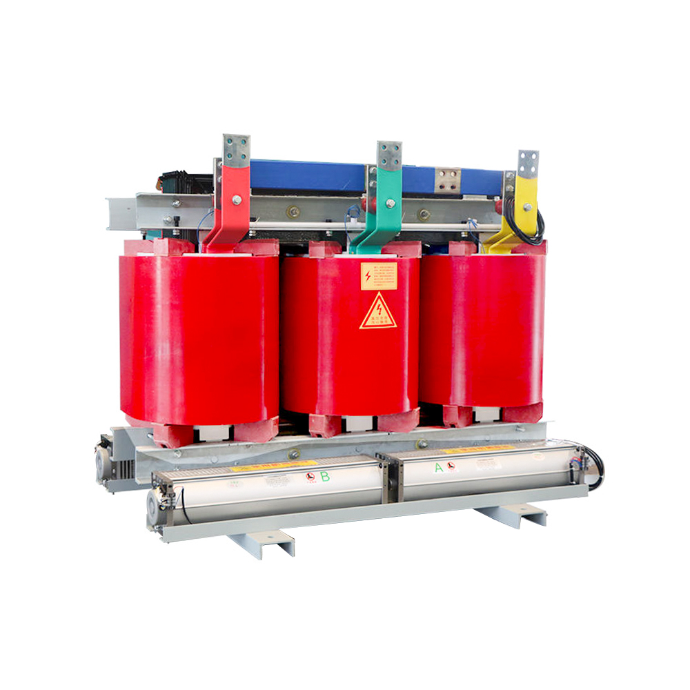 Three-phase Dry-type Transformer with Silicon Steel CoreThis epoxy-cast dry-type transformer suits indoor sites where fire safety matters. Vacuum-cast copper windings resist moisture and short circuits, and low-loss designs help it operate efficiently in high-rise and tunnel settings.View Product →
How to Size a 3 Phase Electric Transformer Correctly
Sizing starts from the connected load, applies a demand factor, adds planned expansion margin, and only then converts the result into kVA using the three-phase formula. A transformer selected this way runs at 60-75 percent loading, which is the efficiency and life sweet spot.
- List every motor, drive, heater and lighting load in kVA or kW, with the power factor of each motor.
- Apply a demand factor based on real operating patterns: 1.0 for continuous process lines, 0.6-0.8 for general manufacturing.
- Add a 20-25 percent margin for future machines; a unit loaded above 85 percent overheats faster and loses efficiency.
- Convert the total using kVA = 1.732 x line voltage (kV) x line current (A). For kW loads, kVA = kW / power factor.
- Round up to a standard nameplate rating: 100, 160, 250, 400, 630, 800, 1000, 1250 or 1600 kVA.
- Verify impedance, off-circuit tap range and short-circuit withstand against the low-voltage switchgear rating.
No-load losses of three 500 kVA three-phase transformers, typical published values.
The chart shows why core material is the first question a buyer should ask. An amorphous alloy core cuts no-load losses by roughly 65 percent compared with a conventional grain-oriented silicon steel core, and by more than 75 percent compared with a typical dry-type unit. Because no-load losses run whenever the transformer is energized, they dominate the lifetime energy bill for lightly loaded units.
When the load includes variable-frequency drives or six-pulse rectifiers, specify a K-factor rated unit or add a harmonic filter. Nonlinear loads produce 5th and 7th harmonic currents that raise winding temperature beyond what the nameplate kVA implies.
Where the Transformer Sits in the Distribution Chain
In a typical industrial or commercial network, the 3 phase electric transformer is the bridge between the medium-voltage utility feed and the low-voltage switchgear that feeds the loads. Getting this interface right prevents the most common and most expensive electrical failure modes.
Transformer impedance defines the prospective short-circuit current on the low-voltage side. If an existing transformer is replaced with a lower-impedance unit, fault current can rise above the breaking capacity of the installed LV switchgear. If a higher-impedance unit is selected, voltage regulation under motor starting degrades. Both values must be checked together.
For facilities that need the full chain in one package, a compact substation integrates the ring main unit, transformer and low-voltage distribution into a single enclosure. This is the fastest way to energize a new site because the assembly is factory-tested before transport.
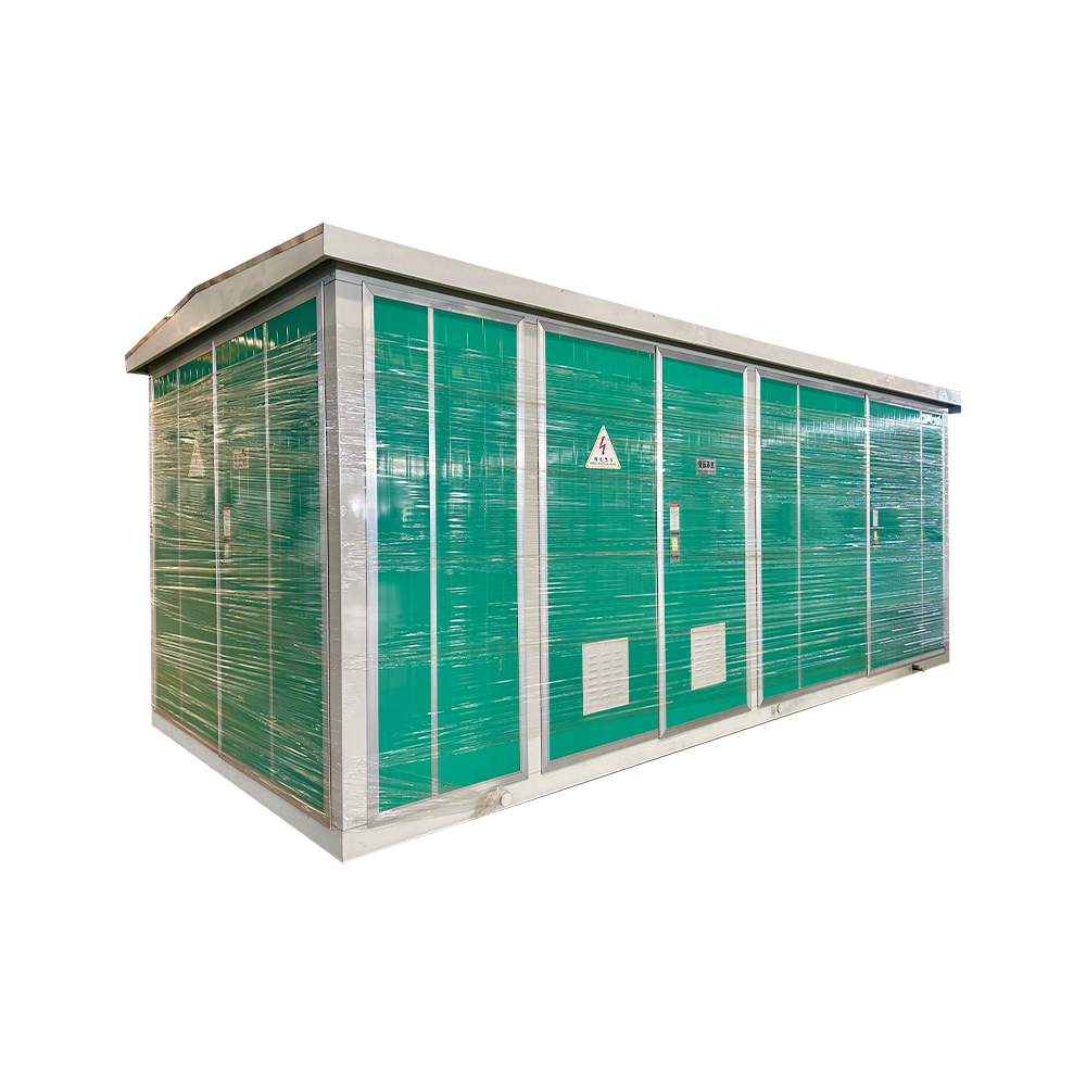 Compact Substation Combining Ring Main Unit and TransformerThis factory-tested unit integrates medium-voltage switching, transformer, and low-voltage distribution in one enclosure. It enables fast site energization with low loss, minimal maintenance, and a small footprint for new projects.View Product →
When a project calls for separate equipment, the medium-voltage ring main units and low-voltage switchgear available in the manufacturer catalog can be reviewed before the single-line diagram is finalized.
Frequently Asked Questions About 3 Phase Electric Transformers
What is the difference between a single-phase transformer and a 3 phase electric transformer?
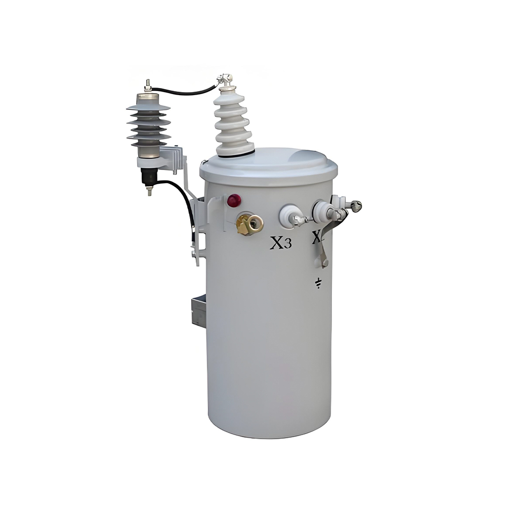
A single-phase transformer has one primary and one secondary winding and delivers pulsating power. A 3 phase electric transformer has three winding sets on a shared magnetic core and delivers constant power to balanced loads, which makes it about 15-20 percent lighter per kVA and better suited to motor loads.
Can three single-phase transformers replace one three-phase transformer?
Yes. Three single-phase units can be connected as a three-phase bank, and this configuration is sometimes used for redundancy and transportability. It costs 15-20 percent more, occupies more floor area and produces higher total losses than a single three-phase unit of the same rating.
How do I calculate the kVA rating for a new production line?
Sum the full-load kVA of every motor and drive, apply a demand factor of 0.6-0.8 for intermittent duty, add 20-25 percent for future expansion, then select the next larger standard rating. A 400 kVA unit is the right choice for a measured demand of about 300-320 kVA.
What does Dyn11 on the nameplate mean?
D means primary delta connection, y means secondary wye connection, n means the neutral of the wye secondary is brought out, and 11 means the secondary voltage lags the primary by 30 degrees. Dyn11 is the most common vector group for medium-voltage step-down distribution transformers in many markets.

 Contact

Contact
-

wxj.810@163.com
-

+86-523-82962116
-

No. 111, Guoqing East Road, Chengdong High-tech Industrial Park, Taixing City, Jiangsu Province, China
Copyright © 2026 by Jiangsu Hengyuan Transformer Co., Ltd. Rights Reserved.
