 English
 русский
 Español
 عربى
عربىOil Filled Distribution Transformers: Core Loss, Cooling, and Selection Guide
Content
- 1 What an Oil-Immersed Distribution Transformer Is
- 2 Oil-Filled Distribution Transformer Losses: Core Material Decides the Bill
- 3 Cooling Classes: ONAN, ONAF, ONWF and Real Duty Limits
- 4 Distribution Transformer Specification Checklist for Substation Projects
- 5 Maintenance That Keeps an Oil-Filled Distribution Transformer Reliable
- 6 Frequently Asked Questions on Oil-Filled Distribution Transformers
- 6.1 What is the difference between an oil filled distribution transformer and a dry-type transformer?
- 6.2 How long can an oil filled distribution transformer operate?
- 6.3 Can an oil filled distribution transformer be installed indoors?
- 6.4 Which oil should a distribution transformer use, mineral or ester?
A 630 kVA oil filled distribution transformer with a conventional silicon steel core can consume roughly 7,000 kWh of no-load losses every year simply by staying energized. Switch the core to amorphous alloy and that figure drops toward 3,000 kWh, a gap that procurement teams multiply across every feeder they operate. That is why utility and industrial buyers now judge oil filled distribution transformers by loss evaluation, cooling class and core material before they compare purchase prices.
What an Oil-Immersed Distribution Transformer Is
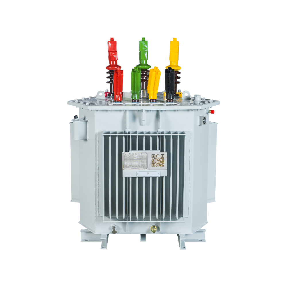
An oil filled distribution transformer is a sealed steel tank that contains a three-phase magnetic core and windings submerged in insulating oil, which isolates live parts and carries heat away toward the tank wall.
The unit converts medium voltage, typically 6 kV, 10 kV, 15 kV, 20 kV or 35 kV, down to the 400/230 V level used by commercial, agricultural and industrial loads. As the windings heat up, the oil rises, gives up heat through the radiator fins on the tank wall, and sinks again in a continuous loop. With no fans or pumps, this ONAN configuration is the quietest and most reliable cooling mode available.
- Magnetic core and high-voltage/low-voltage windings in copper or aluminum
- Tank, radiator fins, and conservator tank for oil expansion
- Buchholz relay for gas detection in conservator-type units
- Pressure relief device and oil temperature indicator
Oil-Filled Distribution Transformer Losses: Core Material Decides the Bill
Core material is the single largest driver of long-term operating cost for oil filled distribution transformers, because no-load losses run around the clock whenever the unit is energized, even at zero load.
No-load loss, or iron loss, comes from hysteresis and eddy currents in the core. Load loss, or copper loss, appears in the windings and grows with the square of the current. Below 2,000 kVA, the two core technologies that matter are grain-oriented silicon steel and amorphous metal alloy. Amorphous cores cut hysteresis loss sharply, but the alloy saturates at a lower flux density, so the core is larger and the first cost is higher. In distribution service, the operating-cost saving typically pays back the price difference within 3 to 6 years.
Jiangsu Hengyuan Transformer Co., Ltd. builds the 6-35 kV distribution range in both core technologies. The amorphous alloy core version is the preferred choice when the client capitalises losses over the full service life, because the loss saving pays back the core premium within a few years.
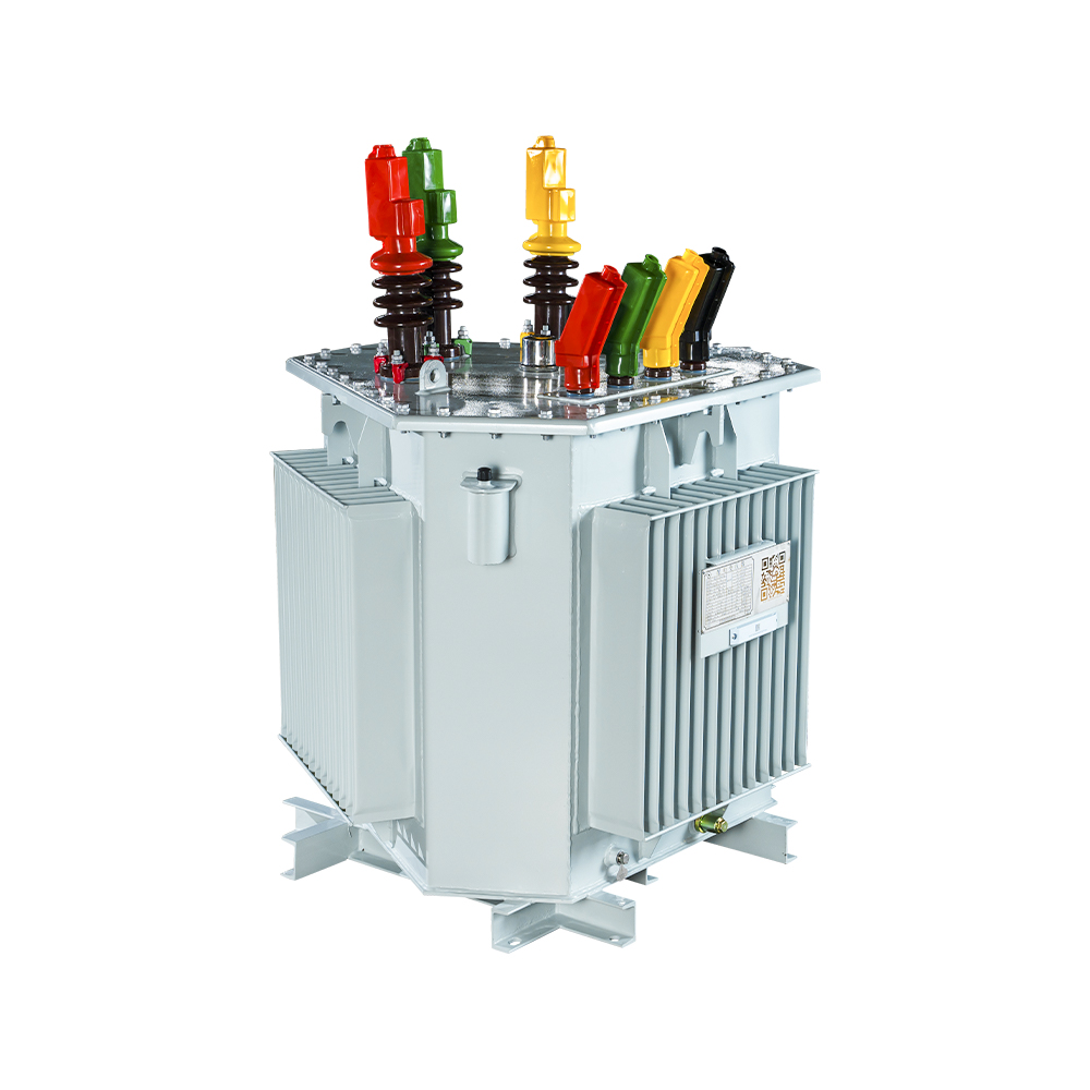 Amorphous Alloy Core Oil-immersed TransformerThis transformer uses amorphous alloy core for ultra-low losses, reducing energy consumption and emissions while offering high reliability and low noise for distribution networks.View Product →
Cooling Classes: ONAN, ONAF, ONWF and Real Duty Limits
The cooling class stamped on the nameplate defines how much continuous load the transformer can carry and whether that rating changes when fans or pumps are switched on.
| Cooling class | Coolant and method | Effect on rating | Typical application |
| ONAN | Oil natural, air natural | Base rating, no auxiliary load | Standard distribution units |
| ONAF | Oil natural, air forced | +20-30% with fans running | Seasonal peak load windows |
| ONWF or OFAF | Oil natural/forced, water forced | High continuous rating with auxiliary systems | Indoor industrial plants |
IEC 60076 sets the standard temperature-rise limits at 60 K for top oil and 78 K for the winding hot spot in oil-immersed units. A unit designed for a 40 C ambient must therefore keep its top-oil temperature below 100 C in continuous service. Sealed-tank designs remove the conservator and keep oil away from outside air, while conservator-type units add a breather with a silica gel dryer.
Distribution Transformer Specification Checklist for Substation Projects
A complete specification fixes the electrical parameters, loss class, cooling, insulating fluid, accessories and the factory test procedure before the purchase order is issued.
- Primary voltage, vector group and tap range - Dyn11 is the dominant vector group for 400/230 V secondary distribution networks.
- Impedance voltage and short-circuit withstand - usually 4% in this class; confirm the maximum through-fault current the unit must survive.
- Loss evaluation prices - state the capitalised price per watt of no-load and load loss; this single input decides the core material and conductor size.
- Cooling class and ambient design temperature - use the highest measured site temperature, not the annual average, as the thermal design point.
- Insulation fluid - mineral oil for standard sites; natural ester where fire safety or biodegradability drives the decision.
- Accessories - Buchholz relay, oil temperature indicator, pressure relief device, drain and sampling valves, and tap changer position indicator.
- Compliance standard - the IEC 60076 series, plus the grid operator's earthing and routine test requirements.
The decision formula every project engineer should apply is purchase price plus annual no-load loss times its capitalisation rate plus annual load loss at the expected load factor times its rate, summed over the evaluation period. Ignoring any of the three produces the wrong transformer.
For budget-driven add-on units inside existing networks, the silicon steel strip core version remains the standard choice and simplifies spares and servicing across a mixed fleet.
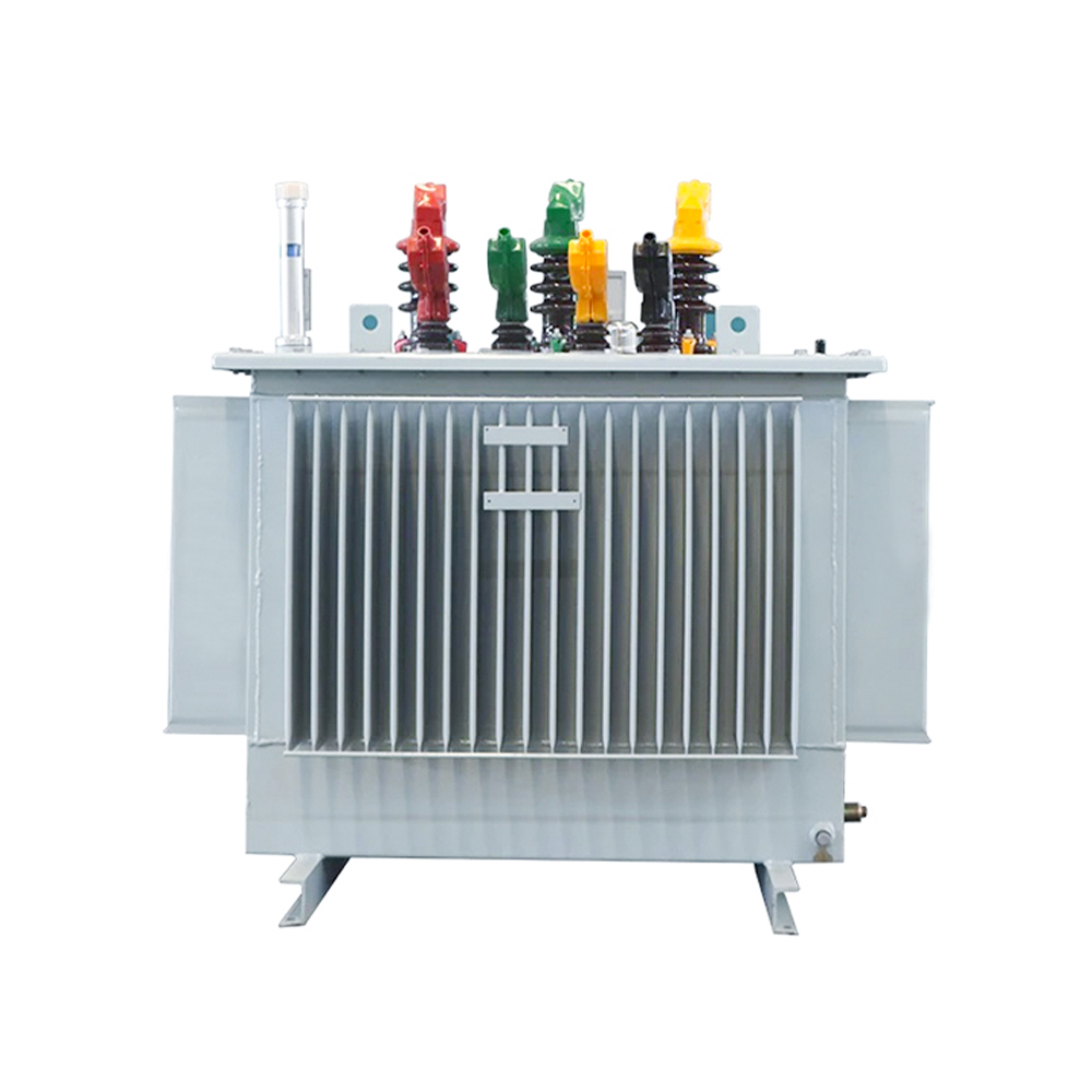 Silicon Steel Strip Core Oil-immersed TransformerA fully sealed, low-loss transformer with corrugated plate cooling, offering minimal maintenance and compact footprint for cost-effective distribution in existing networks.View Product →
Hermetically sealed, no conservator; compact footprint; oil never contacts outside air; lower maintenance, but fluid sampling is more involved.
Expansion tank with breather; internal pressure stays near constant; DGA sampling is straightforward; preferred above 1,000 kVA and for frequent inspection regimes.
For project sites that need the transformer delivered together with medium-voltage switching and low-voltage distribution, a prefabricated compact substation packages a ring main unit, transformer and LV panel in one enclosure.
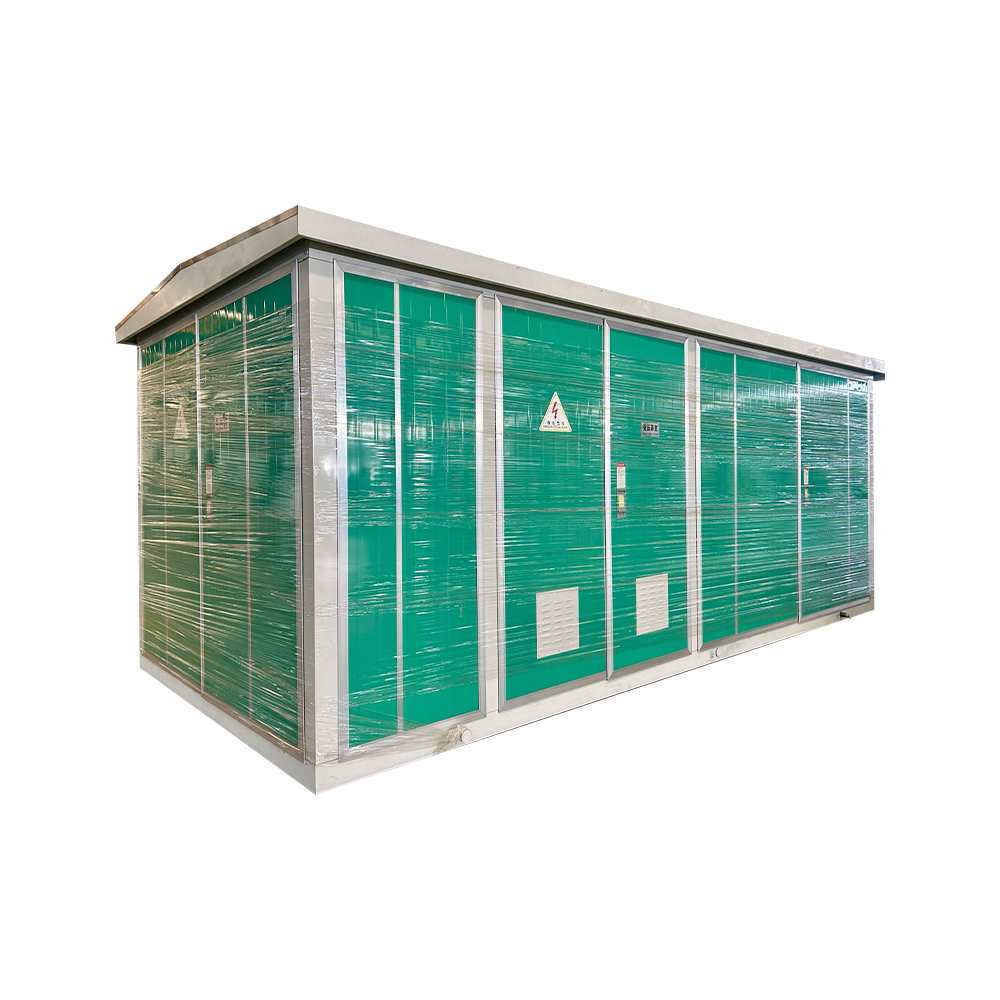 Compact Substation with Transformer and SwitchgearCombines ring main unit, transformer and LV panel in one enclosure, reducing footprint and installation time while providing reliable, low-loss power distribution for project sites.View Product →
Maintenance That Keeps an Oil-Filled Distribution Transformer Reliable
Oil quality, not winding age, determines whether an oil immersed distribution transformer stays in service for 30 years or fails after ten.
- Annual dissolved gas analysis (DGA) - one oil sample catches thermal and electrical faults months before they cause failure.
- Quarterly visual checks - oil level, Buchholz relay, desiccant colour and any leak on radiators or tank seams.
- Breather service - replace or regenerate the desiccant before moisture enters the main tank; moisture ages paper insulation faster than temperature does.
- Pre-season fan and protection test - verify thermostats, forced-air fans and the pressure relief device before summer peak loading.
- Outage-based tap changer check - measure winding resistance at each tap and inspect contact wear, typically every 3 to 5 years.
If DGA shows dissolved gas rates doubling between samples, plan follow-up tests immediately. Most winding and insulation failures give measurable warning long before catastrophic failure.
Furan compounds and moisture content in the oil indicate the condition of the paper insulation, which is the true wear component of an oil filled transformer. Trending these values every year provides the data needed to justify reconditioning or replacement decisions.
Frequently Asked Questions on Oil-Filled Distribution Transformers
The four questions below settle most procurement arguments in real distribution projects.
What is the difference between an oil filled distribution transformer and a dry-type transformer?
The oil-filled unit uses oil for both cooling and insulation, giving a higher overload margin and lower noise at the same rating. A dry-type unit uses air or cast resin and eliminates fire and oil containment concerns, which makes it the preferred option for indoor installations with strict fire codes.
How long can an oil filled distribution transformer operate?
With disciplined maintenance, including annual DGA, moisture control and breather service, a distribution transformer commonly stays in service for 30 years. Paper insulation is the aging component; keeping its moisture content low is the single most effective way to extend life.
Can an oil filled distribution transformer be installed indoors?
Yes, when the room provides oil containment, fire protection and ventilation. Many indoor projects select natural ester fluid instead of mineral oil because ester raises the flash point above 300 C and degrades harmlessly in the environment.
Which oil should a distribution transformer use, mineral or ester?
Mineral oil is the default for mainstream projects because of cost, supply and established maintenance practice. Natural ester is chosen where fire risk, environmental protection or sustainability reporting dominates. Both fluids work in the same tank design with minor adjustments to clearances and gaskets.
Before you request a quotation, complete a one-page loss evaluation sheet: the price per watt of no-load and load loss, the site's peak ambient temperature, the load profile and the expected service life. A manufacturer that translates those numbers into a specification is one that understands distribution network economics.
Recommended Products

 Contact

Contact
-

wxj.810@163.com
-

+86-523-82962116
-

No. 111, Guoqing East Road, Chengdong High-tech Industrial Park, Taixing City, Jiangsu Province, China
Copyright © 2026 by Jiangsu Hengyuan Transformer Co., Ltd. Rights Reserved.
